Do you have a question about the Garmin GTX330 and is the answer not in the manual?
Provides an overview of the GTX 330/330D Mode S Transponder and its installation.
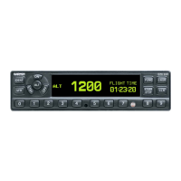
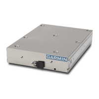
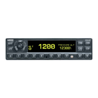
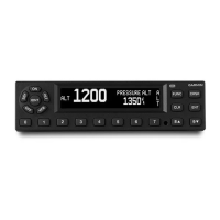
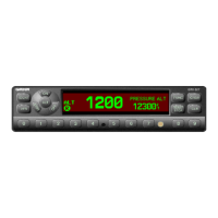
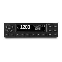
Details the GTX 330 and GTX 330D units, including ES option and design specifications.
Explains Automatic Dependent Surveillance-Broadcast and Traffic Information Service features.
Lists the various interface connections available on the GTX 330 rear connector.
Covers general, physical, and power specifications, including TSO/ETSO compliance.
Details TSO/ETSO compliance, deviations, and aircraft station licensing requirements.
Outlines the warranty terms and conditions for Garmin avionics products.
Introduces hardware and optional accessories for GTX 330 installation.
Lists available GTX 330 models, part numbers, and configurations.
Discusses installation factors like equipment interfacing, antenna mounting, and cable routing.
Covers antenna mounting considerations, location, and installation procedures.
Provides guidelines for routing cables, cable types, and attenuation limits.
Details FAA approval requirements for installations on pressurized aircraft.
Discusses cooling requirements and optimal viewing angles for the GTX 330 display.
Covers the steps for mechanically installing the transponder unit into its rack.
Instructions for unpacking the unit, inspecting for damage, and retaining packaging.
Details electrical connections via the 62-pin connector and associated hardware.
Guidance on installing the required circuit breaker placard.
Procedures for verifying operation and configuration after installation.
Lists and defines the functions of pins on the J3301 rear connector.
Details power input requirements and lighting bus connections.
Explains temperature input usage for OAT display and density altitude computations.
Covers altimeter inputs, selection priority, and wiring for gray code and serial data.
Describes discrete outputs and inputs, including suppression and alert signals.
Details RS-232 and ARINC 429 data characteristics and configurations.
Explains transponder operation, function selection, code entry, and display functions.
Guides users through configuring various settings via the transponder's interface.
Configures display modes, backlight, key lighting, contrast, audio, and traffic messages.
Configures ARINC 429, RS-232 inputs/outputs, and data formats for various avionics.
Sets aircraft details, Mode S address, Flight ID, ADS-B, EHS, and other operational parameters.
Details equipment connections and parameters required for Mode S Enhanced Surveillance.
Provides Supplemental Type Certificate details for aircraft installation.
Outlines maintenance and airworthiness requirements for the unit.
Shows dimensional specifications and physical layout of the GTX 330 unit.
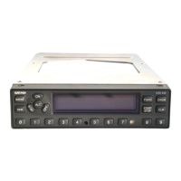
Illustrates connector and rack assembly details for mounting the unit.
Provides panel cutout dimensions for installation options.
Details wiring for connecting GTX 330 to Garmin 400/500 series units.
Shows wiring for connecting GTX 330 to Garmin GNS 480 (CNX80).
Illustrates wiring for dual transponder configurations, including display and altitude connections.
Wiring for GTX 330 with TIS and TCAD/TCAS systems.
Wiring diagram for GTX 330 w/ES to GDL 90.
| Category | Transponder |
|---|---|
| Reply Frequencies | 1090 MHz |
| Altitude Reporting | Yes |
| Compliance | DO-260B |
| Transmit Power | 250 W |
| Frequency Range | 1030-1090 MHz |
| Power Output | 250 W |
| Current Draw | 1.5 A |