Do you have a question about the Garmin Smartpump and is the answer not in the manual?
Important notes related to connecting the SmartPump to the hydraulic system.
Procedure to configure the pump for boats with unbalanced steering cylinders.
Details on the specifications for pump ports and associated fittings.
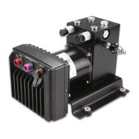
The Garmin SmartPump is an autopilot pump designed to enhance the operation of your vessel by interacting with the hydraulic steering system based on commands from the autopilot system. It is a critical component for automated steering, allowing for more precise control and navigation.
The SmartPump's primary function is to steer your boat by manipulating the hydraulic steering system. It receives commands from the autopilot system and translates these into hydraulic movements, enabling the vessel to maintain a course, follow a route, or perform other automated steering tasks. The pump is designed for use exclusively with Garmin autopilot systems, ensuring seamless integration and optimal performance. It is crucial that the steering system it connects to has a vented reservoir; otherwise, the pump could be damaged. The pump is equipped with five hydraulic-connector fittings, though typically only three are used in standard installations. These include H1 and H2 ports (recommended for helm and cylinder connections), C1 and C2 ports (alternative connections), and a return line port. A bypass valve is also present for hydraulic bleeding.
Before installation, it is essential to identify the type of hydraulic steering system on your boat and consult the provided hydraulic diagrams to determine the best mounting location and connection method. The pump should ideally be installed in a dry location, protected from water and weather. For optimal performance, especially with larger steering cylinders or systems requiring higher fluid pressure, the pump should be mounted as close to the cylinder as possible, with no more than 3 meters (10 feet) of hydraulic hose connecting them. The pump can be mounted horizontally, or vertically with the pump head connectors facing up if horizontal mounting is not possible.
When connecting the hydraulic hoses, T-connectors and shut-off valves (not included) are recommended. Shut-off valves allow for easy pump isolation and removal for service without disrupting the boat's normal steering. It is critical to use hydraulic hose that is -4 [6 mm (1/4 in.) ID] or larger with machine-crimped or field-replaceable fittings rated for a minimum of 1000 psi. When applying thread sealant to fittings without an O-ring, use a liquid thread sealant like Loctite 567, and strictly follow the manufacturer's cure time instructions to prevent leaks and system damage. Thread seal tape or putty should never be used, as debris can enter the hydraulic system and cause malfunctions.
The SmartPump must be configured if the boat has an unbalanced steering cylinder. This involves removing and re-inserting the pistons in the pump manifold in the unbalanced configuration, where the tip of the piston points out of the manifold. After any configuration changes or hydraulic system work, it is imperative to bleed all air from the hydraulic system before using the autopilot.
To ensure the longevity and proper functioning of the SmartPump, several maintenance considerations are important. After completing the installation and bleeding the hydraulic system, it is recommended to apply a marine corrosion inhibitor spray to the SmartPump. Garmin advises re-applying this spray annually to maintain corrosion resistance and extend the pump's life.
Software updates are also a key aspect of maintenance. After the autopilot installation, the software should be updated before proceeding with the configuration process. If the autopilot system is connected to a NMEA 2000® network with a Garmin chartplotter, updates can be performed using the chartplotter. If not, a NMEA 2000 Network Updater (sold separately) is required. Keeping the software updated ensures the pump operates with the latest features and bug fixes.
When configuring the pump for an unbalanced cylinder, it is crucial to keep all parts clean and free of dust and debris to prevent damage. If the check valves are removed after bleeding the hydraulic system, the system must be bled again, as air may be introduced. When disconnecting connectors sealed with liquid sealant, care must be taken to prevent any slivers or debris from entering the hydraulic system. Following these guidelines will help maintain the SmartPump's performance and reliability over time.
| Voltage | 12V DC |
|---|---|
| Amperage | 5A |
| Operation | Automatic |
| Power Source | 12V DC |
| Material | Plastic |
| Operating Temperature | 32° to 140°F (0° to 60°C) |