Installation
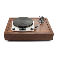
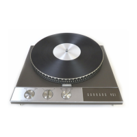
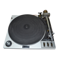
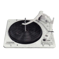
The Garrard Model 301 Transcription Motor
should be assembled to a substantial wooden motor board
which should be cut out and drilled to the template sup
plied with each unit or to the dimensions given on
Diagram 11. The motor should be assembled to the board,
using the rubber washers supplied, between the unit plate
and the board to prevent any distortion of the plate due
to any possible inaccuracies in the board.
Insert the screws and assemble the washers and nuts
as indicated in Diagram 5 tightening up the nuts equally
a little at a time, then securely tightening up the lock nuts.
To protect the electric motor during transit it is
firmly clamped by means of two transit screws, Diagram 5.
These screws, the heads of which are coloured red,
must be unscrewed as far as they will go to release the
motor clamp plate which allows the motor to float freely
on its suspension springs. To clamp the motor for transit
purposes the two motor transit screws should be tightened
up.
The pickup to be used should be mounted on the
board according to the manufacturers’ instructions.
The motor should be fixed to the motor board as
described above. This, however, may not always be
possible due to the presence of extraneous vibration
caused by shutting the cabinet lid or drawer or walking
across the floor on which the cabinet is standing.
In these cases, the motor board should be spring
mounted in the cabinet with the spring mounting assembly
provided as illustrated on Diagram 7. The cabinet board
being as shown in Diagram 8. With the motor and turn
table in position, there should be a gap of about to
between two boards. A reduced dimension template for
this board is given in Diagram 12.
13