On final installation the motor should be levelled
by adjusting the inner nuts of the spring suspensions,
removing the lower mit, triangular washer, and lock nut
to do so, replacing them when the unit is level.
The level should be checked by means of a spirit
level placed on a record on the turntable.
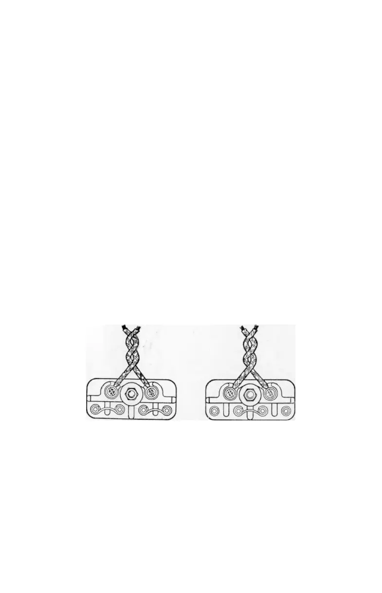
A suitable set of four spring mounting assemblies
is supplied with each transcription motor and they
should be assembled as shown on Diagram 6. Should
the motor board be thicker than the fixing holes should
be recessed
\\"
diameter from underneath to bring the
thickness of the board to from the top.
Before assembling the motor into the cabinet con
nect the power supply lead, if not already fitted, to the
power supply terminal block situated at rear of motor,
making sure that the lead is securely clamped in the cord
grip adjacent to the block. Check that the voltage range
is set correctly for the power supply to be used; the links
should be set as shown on terminal block cover and
Diagrams 9 and 10. The motor pulley should also be
Set for 100/130 volts
Set for 200/250 volts
Diagram 9 Diagram 10
checked to see that the correct one for>the frequency of
the power supply is in position on the motor, a nickel
finished one for 50 cycles, a brass one for 60 cycles.
15