D
daviseddieSep 13, 2025
Why do GASTRON Gas Detectors display H/W REV?
- SSuzanne BarnesSep 13, 2025
If your GASTRON Gas Detectors display 'H/W REV', this could be due to a defective MPU inside the transmitter.
Why do GASTRON Gas Detectors display H/W REV?
If your GASTRON Gas Detectors display 'H/W REV', this could be due to a defective MPU inside the transmitter.
| Brand | GASTRON |
|---|---|
| Model | GTD-2000Tx |
| Category | Gas Detectors |
| Language | English |
Lists essential technical parameters like measuring type, range, accuracy, and warranty.
Details physical dimensions, weight, mounting, and material specifications.
Covers input voltage, wattage, analog output current, and wiring requirements.
Outlines operating temperature, humidity, pressure range, and air velocity limits.
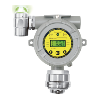
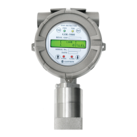
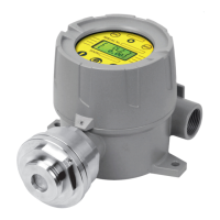
Identifies and describes the various physical components of the gas detector.
Explains the function of the LED indicators (green, red, yellow) and buzzer status.
Provides instructions on how to safely remove the housing cover of the detector.
Details the layout and connections of the Main Printed Circuit Board (PCB).
Explains the terminal block layout and connection points on the Main PCB.
Describes how to wire the detector for 4-20mA source operation.
Details the wiring procedure for 4-20mA sink operation.
Explains the wiring for 4-20mA 3-wire sink operation.
Provides guidance on calculating and determining the maximum installation cable length.
Describes the display and self-test sequence upon powering on the detector.
Explains the normal operation screen and how measurements are displayed.
Outlines the sequence of operations and mode transitions within the detector.
Provides a comprehensive table of menu options, parameters, and default settings.
Details how to access and configure various settings in the Program Mode.
Explains the process for entering and performing calibration procedures.
Provides step-by-step instructions for performing zero calibration.
Details the procedure for performing span calibration with standard gas.
Describes how to configure alarm levels, types, and latch settings.
Lists common fault messages, their conditions, and potential causes.
Provides solutions and steps to recover from identified faults.
Shows dimensional drawings for the standard GTD-2000TxW gas detector.
Displays dimensional drawings for the GTL-100 warning light accessory.
Illustrates the detector with the warning light connected, showing overall dimensions.
Guides on choosing an appropriate installation location based on safety regulations.
Provides criteria for selecting installation sites according to gas safety acts.
Lists essential precautions to follow during the installation process.