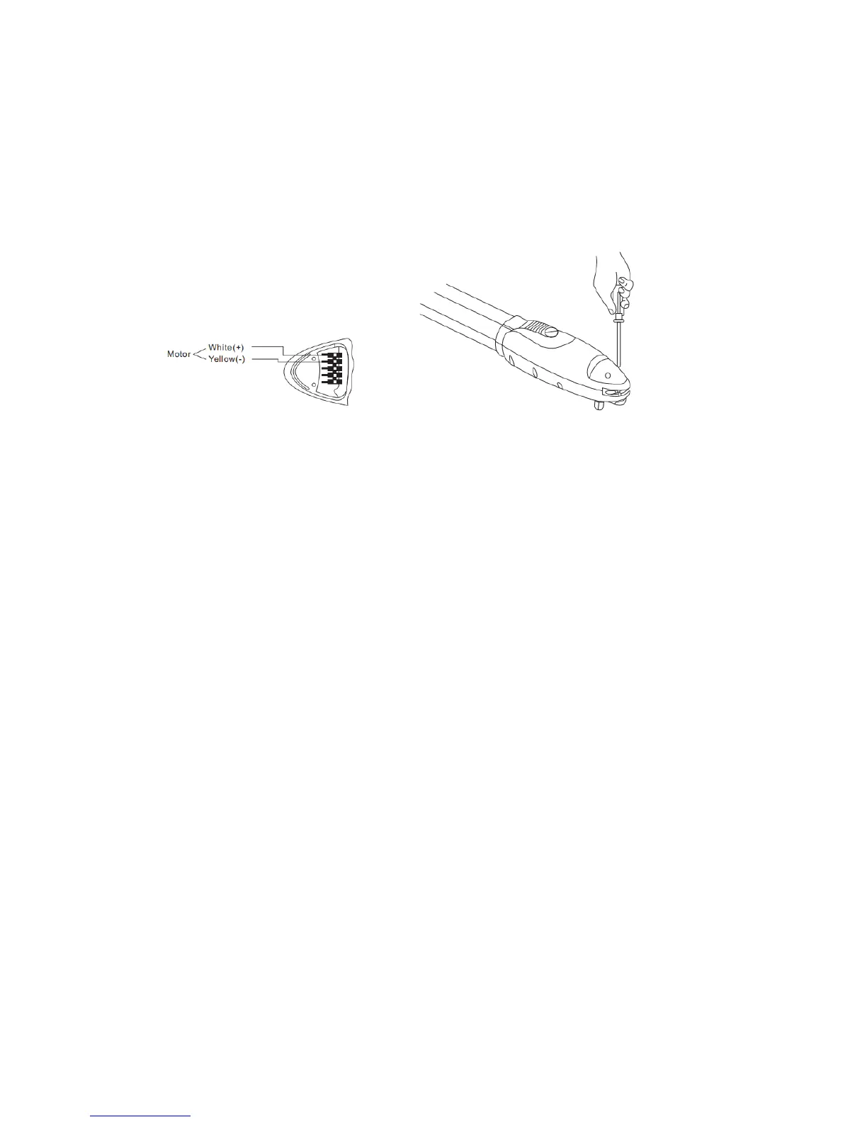
Connect the motor power cable as shown in Figure 27
The actuator is not pre-wired. Use 2 conductor 14-gauge stranded wire and feed it up through the
strain relief nut.
Next, securely fasten to terminal blocks red to positive (white) and black to negative (yellow)
(you may use white and yellow stranded wire if available)
Close the gear motor cover by tightening the two screws as shown in Figure 28
Figure 27 Figure 28
Mount the Control Box
Locate a position in the most convenient spot close to the primary actuator and mount the control
box using such fasteners as you see fit. Also mount a watertight junction box underneath the
control box for 110vac.
Single gate installation -
Run the two pair wire from the actuator to Control Box
Bi-parting gate installation -
Connect a two pair wire as before to the secondary actuator and run the wire to the control box. It
is recommended to use 3/4” conduit under the driveway, fashioned neatly to the control box or to
a watertight junction box (and from there to the control box)
You will have to punch out the existing knockouts at the bottom of the control box for the
secondary wires and any additional access controls wire. It is recommended to seal the holes with
silicone caulk.