Fasten the gate attach bracket nut tightly and then loosen it 1/2 turn so actuator can pivot.
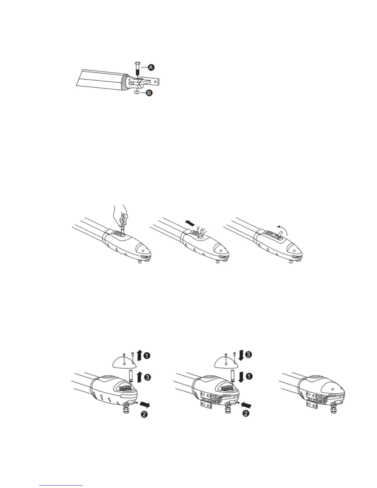
Open the gear motor cover and then take out the mounting pin as below Figure 25.
Mount the actuator to the hinge post bracket using supplied pin and insert the mounting bolt into
the gate attach bracket.
This is the position of the gate in the closed position and cannot be changed once finally drilled
and bolted. Be sure the actuator is level and the gate is in the desired permanent closed position.
Gear Motor Release
Turn the round plate on the release part to “OPEN” position, See Figure 29
Push out the release part to the end. See Figure 30
Use the release key to turn the pin ani-clockwise to the end. See Figure 31
Figure 29 Figure 30 Figure 31
With the gear motor unlocked, slowly swing the gate open until the extension tube is fully
extended. The top part of the post bracket will self-adjust to the correct position and can then be
tightened securely. (remember, you had left it finger tight)
Test the bracket positions a few times and when satisfied they are in the proper position, drill and
bolt the gate attach bracket permanently. There are no limits to set so at this point the actuator is
ready to be powered up and used.
Figure 25 Figure 25.1 Figure 25.2