FIGURE 17
“C” value is 139mm (5-1/2”)
“D” can be measured from the gate easily
“A” = “C” + “D”
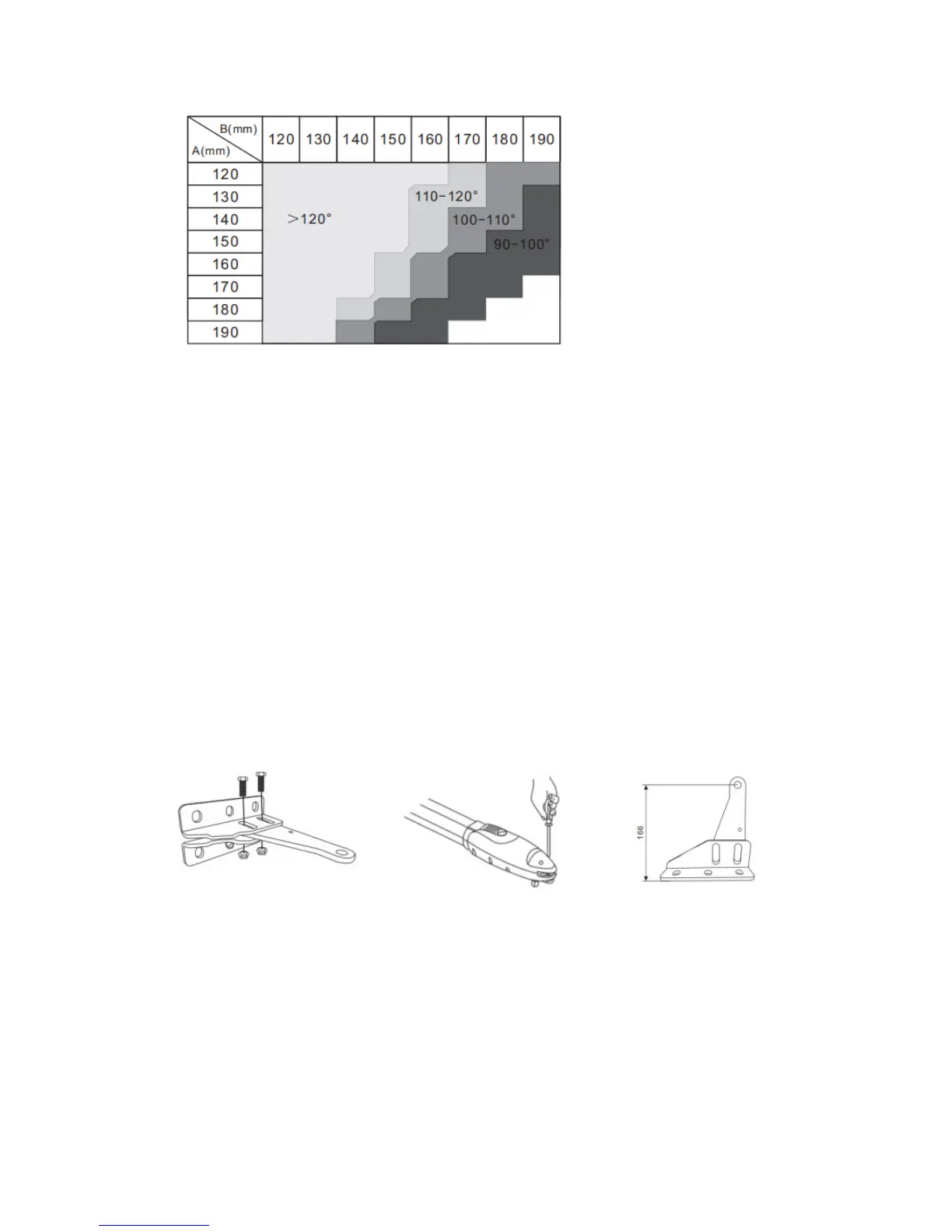
The value of “B” can be calculated from the value of “A” and the leaves opening angle. Example:
If “A” =160mm (6-1/4”) with the leaves opening angle of 100 degrees, then the value of “B” is
approximate 190mm (7-1/2”)
NOTE: Please make sure “B” and “A” are similar or the same in value that the leaves can be
operated smoothly to reduce the burden of the motor.
NOTE: A 120-degree opening may be obtained but 110 degrees is the recommended limit.
Installation of the Gear Motors
1. Mount Post Bracket
Choose the desired dimensions of the motors and position to be installed.
Be sure mounting surface the brackets will be installed on is smooth, vertical and rigid.
Arrange the cable conduit for power supply cable of the motors.
Loosen the two screws and remove the back cover of the motor as shown in photo
Place the gate leaves in the closed position.
Figure 18 Figure 19 Figure 20
Refer to the “B” dimension in figure 17, place the post bracket plate in the correct position on the
mounting surface.
Place the post bracket on the surface to be installed and mark the drilling points then drill 3/8
holes x four through the hinge post and fasten the brackets with nuts and washers. The drawing
below shows tech screws but it is highly recommended to drill all the way through the hinge post
and to use bolts long enough to bolt on the back side.
Make sure the bracket is level. There are two pieces to the bracket. You have already fastened the
post bracket to the post, now bolt the top part of the bracket to the one that has been mounted.