Do you have a question about the Gateway FPD1510 and is the answer not in the manual?
Technical details of the LCD panel, including type, size, and pixel pitch.
Viewing angle, luminance, and contrast ratio of the display.
Sync signal type, voltage level, polarity, and video input signal specifications.
Power adapter input/output and power consumption modes.
Operating temperature, humidity, and MTBF specifications.
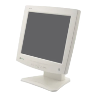
Physical dimensions of the monitor including tilt and swivel.
Net and gross weight specifications of the monitor.
Warnings about critical components for safety and manufacturer replacements.
Guidelines for safely handling the LCD module, including ESD protection and environmental factors.
Instructions on how to turn the monitor on and off using the power button.
Explanation of the power indicator light's color and meaning.
How to use the △▽/▷ buttons for on-screen display adjustments.
Function of the SOURCE/SET button for input selection and confirmation.
How to access and exit the On-Screen Display (OSD) menu.
Steps to remove the tilt/swivel mechanism and the back cover.
Procedure for removing the metal rear assembly from the monitor.
Steps to disconnect and remove the main control PCB assembly.
Description of the input signal switching mechanism.
Function of the video signal processing and scaling components.
Details of the DC/DC converter and voltage regulators.
Role of the microcontroller, EEPROM, and reset IC.
Function of the inverter in powering the backlight.
Procedure for running the factory alignment program and saving FOS data.
Steps for adjusting white balance and drive calibration.
Troubleshooting steps for when the monitor does not power on.
Steps to diagnose and resolve issues where no image is displayed.
Troubleshooting steps for problems related to the clock generator.
Diagnosing issues related to the Display Power Management (DPM) system.
Pin layout and function for the DIP18 package.
Pin layout and function for the SO20 package.