- 7 -
DISASSEMBLY
(a)
(a)
12V
12V
(b)
(b)
(c)
(c)
(c)
(c)
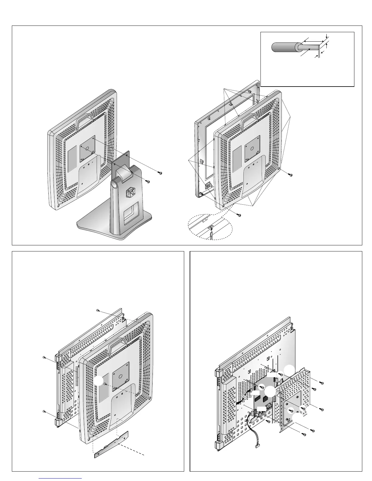
1. TILT/SWIVEL & CABINET ASSEMBLY REMOVAL
(1) Remove two screws (a).
(2) Remove the Tilt/swivel.
(3) Remove two screws (b) from the Back Cover.
(4) Release fourteen latches (c).
(Remove the Front Cover from the Bottom Side.)
(5) Remove the Cabinet assembly.
2. BACK COVER & CONTROL PCB ASSEMBLY
REMOVAL
(1) Remove four screws (a).
(2) Remove the Backcover assembly.
(3) Remove Backcover from the Coltrol PCB ass’y.
(a)
(a)
(a)
(b)
(b)
(b)
(a)
(b)
(a)
(a)
J702
J711
J713
to Control PCB
J1
3. MAIN TOTAL ASSEMBLY REMOVAL
(1) Remove six screws (a).
(2) Remove the Metal Rear.
(3) Disconnect J711, J713 and J702.
(4) Remove four screws (b).
(5) Remove the Main PCB ass’y.
Tip Spec
(a) Width : 5.0~9.0mm
(b) Thickness : 0.6~0.9mm
(c) Depth : less then 10.0mm
Control PCB