The PAN control determines the position of channel signal within the stereo image. This control features a
constant-power characteristic, which means the signal is always maintained at a constant level, irrespective
of position in the stereo panorama.
PAN
The LEVEL control determines the level of the channel signal in the main mix
LEVEL
The CLIP LED”s of the mono channels illuminate when the input signal is driven too high, which could
cause distortion. If this happens, use the TRIM control to reduce the preamp level until the LED does not
light anymore.
CLIP
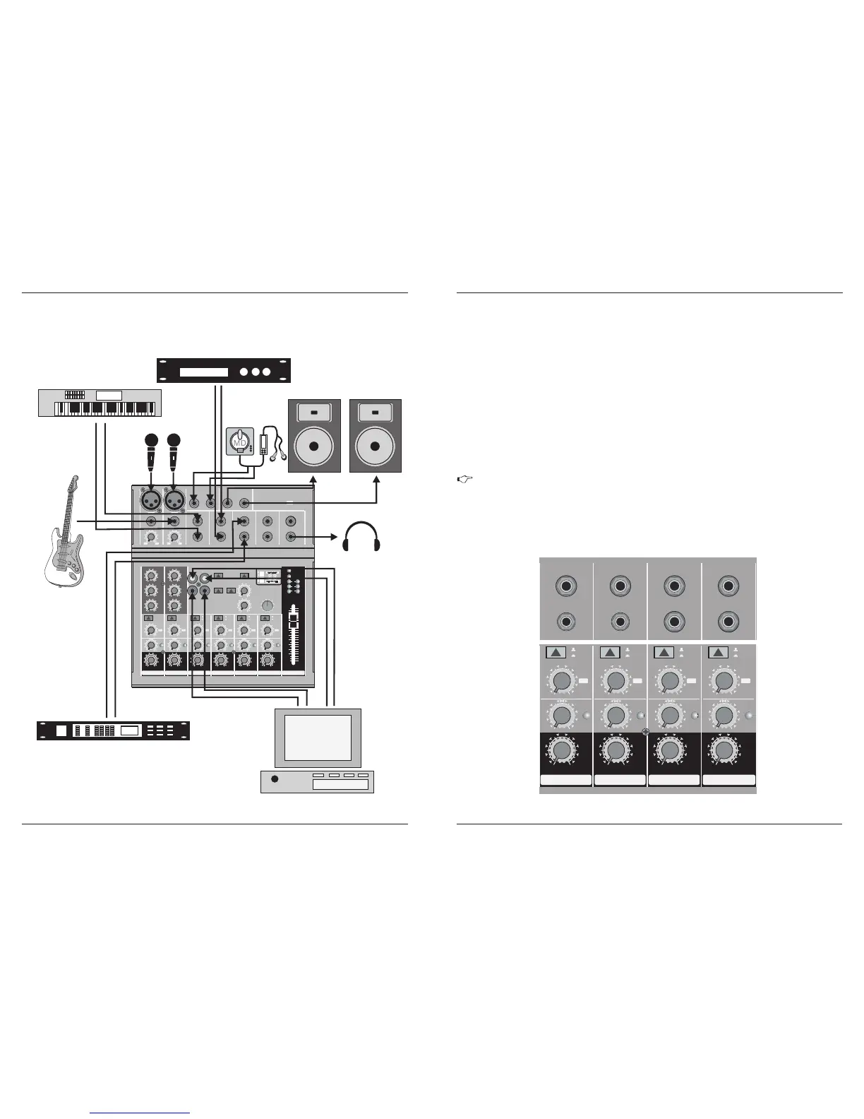
2.2 Stereo channels
6
As the name suggests, the FX sends of the MX mixing consoles are intended to drive effects devices (reverb,
delay, etc.) and are therefore configured post-fader. This means that the mix between dry signal and effect
remains at the level determined by the channel’s aux send, irrespective of the level fader setting. If this were
not the case, the effects signal of the channel would remain audible even when the fader is lowered to zero.
With ME mixing consoles the channel fader is called LEVEL control.
In the MX-6-FX / MX-8-FX / MX-6-FXU / MX-8-FXU, the FX send is routed directly to the built-in effects processor. To
make sure that the effects processor receives an input signal, you should not turn this control all the way to
the left (-∞ ).
Attention: Since the FX path for the effect processor is connected post-fader, the LEVEL
control has to be turned up in order to get this channels signal to the effects processor!
LINE IN 3/4
L
R
MON O
BAL
OR
UNB AL
LINE IN 5/6
MON O
BAL
OR
UNB AL
LINE IN 7/8 LINE IN 9/10
0
- +15
8
L R
BAL
CLIP
0
- +15
8
3/4
LEVEL
0
- +15
8
L R
BAL
CLIP
0
- +15
8
5/6
LEVEL
0
- +15
8
L R
BAL
CLIP
0
- +15
8
7/8
LEVEL
0
- +15
8
L R
BAL
CLIP
0
- +15
8
9/10
LEVEL
+4
-10
+4
-10
+4
-10
+4
-10
MON O
BAL
OR
UNB AL
L
R
L
R
MON O
BAL
OR
UNB AL
L
R
FX FX FX FX
Fig. 2.2: Connectors and controls on the stereo channels
13
3.
APPLICATION
1 2
+10 -40 +10 +60
TRIM
dB/dBu
BAL
OR
UNBAL
LINE
IN
MIC
+10 -40 +10 +60
TRIM
dB/dBu
BAL
OR
UNBAL
LINE
IN
MIC
MAI N OUT
L R L R
CTR L ROOM OUT
LIN E IN 3/4
L
R
MONO
BAL
OR
UNBAL
LIN E IN 5/6
MONO
BAL
OR
UNBAL
LIN E IN 7/8 LIN E IN 9/10
SEN D FX
PHO NES
0
- +15
8
L R
0
-15 +15
0
-15 +15
0
-15 +15
EQ
PAN
HIGH
12 KHz
MID
2.5 KHz
LOW
80 Hz
FX
CLIP
0
- +15
8
1
LEVE L
0
- +15
8
L R
0
-15 +15
0
-15 +15
0
-15 +15
EQ
PAN
HIGH
12 KHz
MID
2.5 KHz
LOW
80 Hz
FX
CLIP
0
- +15
8
2
LEVE L
0
- +15
8
L R
BAL
CLIP
0
- +15
8
3/4
LEVE L
0
- +15
8
L R
BAL
CLIP
0
- +15
8
5/6
LEVE L
0
- +15
8
L R
BAL
CLIP
0
- +15
8
7/8
LEVE L
0
- +15
8
L R
BAL
CLIP
0
- +15
8
9/10
LEVE L
+4
-10
+4
-10
+4
-10
+4
-10
L
R
CD/ TAPE
IN OUT
TAPE
TO MIX
TAPE
TO CTR L
FX
TO CTR L
+48 V
POWER
0
- +15
8
PHON ES
0
- +15
8
FX SEN DS
L R
20
0
6
CLIP
MAIN MIX
10
0
10
15
20
25
30
40
60
8
MONO
BAL
OR
UNBAL
L
R
L
R
PHAN TOM
MONO
BAL
OR
UNBAL
L
R
FX F X FX FX
PROG RAM
(PUS H)
LOW CUT
75Hz
18 dB/ Oct
LOW CUT
75Hz
18 dB/ Oct
M E 1 0 0 2 F X
HIGH QUALITY 14 INPUT 2/2 BUS MIXER 24-BIT DSP FX PROCESSOR
REVERB 00-39
ER/DLY 40-59
MOD 60-73
PITCH 74-79
MULTI 80-99
12
3
12
3
-3
-6
-10
-15
-20
CLP
24-BIT DUAL ENGINE DSP
24-BIT A/D & D/A CONVERTER
88
TAPE
+6. .6 6
MIDI sound module
CD player
Active monitor
Digital Audio workstation
microphone
Guitar
keyboard
3.1 Recording studio
Headphone
MD recorder
MX-6-FX / MX-8-FX
MX-6-FXU / MX-8-FXU
MX-6-FX / MX-8-FX
MX-6-FXU / MX-8-FXU