M
Mark BrownAug 6, 2025
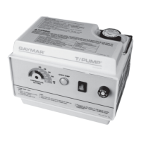
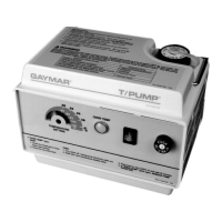
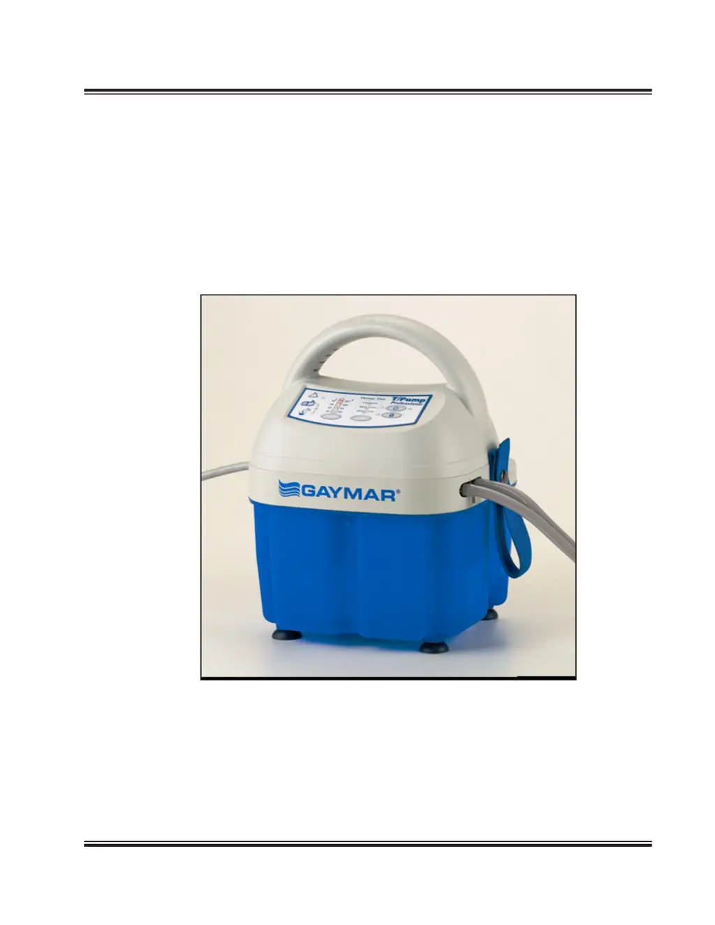
What to do if my Gaymar Medical Equipment T/Pump will NOT turn on?
- EErin BentleyAug 7, 2025
First, ensure the electrical cord is fully inserted into a properly grounded Hospital Grade receptacle. Then, visually inspect the power cord for any defects and replace it if necessary. If these steps don't resolve the issue, the membrane panel may be defective and need replacement. For a defective PC Board, refer to the troubleshooting steps for when the T/Pump will NOT heat.