J. HYDRAULIC CYLINDERS
Attaching the Cylinders
1) Raise the hydraulic cylinder towards the top of the
swing arm.
2) Using a strong grip, pull the eye of the cylinder &
extend inner rod out (Note: First time loosening this
partmaybedifcult.Theprovidedallenwrench+
screwdriver may be inserted through the eye & used
as a “handle” to assist in pulling the rod outward.
After initial assembly, this should no longer be a
concern).
3) Guide the eye of the cylinder through the hook on
the swing arm (as shown). You may need to move
the swing arm slightly forward or back for proper
alignment, then insert the safety pin (located on
lanyard) into hook hole securing cylinder into place.
4) Repeat steps J1-J3 on opposite side.
Note: Ensure that the safety pin is fully engaged
through the hook. You will see the end of the
pin protrude through the bottom of hook.
Note: Attaching the cylinders also engages
the resistance.
Attaching the Hydraulic Storage Clips
5) Place the hydraulic storage clip on the front frame
below the cylinder & secure with the phillips bolt &
screwdriver included. Repeat on opposite side.
Storing the Cylinders
Remove safety pin (on lanyard) from hook. Carefully
disengage the eye of the cylinder from hook on swing
arm. Push rod back into cylinder. Lower hydraulic
cylinder down & push it gently into the hydraulic
cylinder storage clip. Repeat on opposite side.
CAUTION: Hydraulic cylinders MUST be disconnected
& in storage clip position prior to folding
unit. See Owner’s Manual for “Storing Your
Gazelle” instructions.
WARNING: When in use, the cylinders get very hot.
DO NOT touch & please keep children
away.
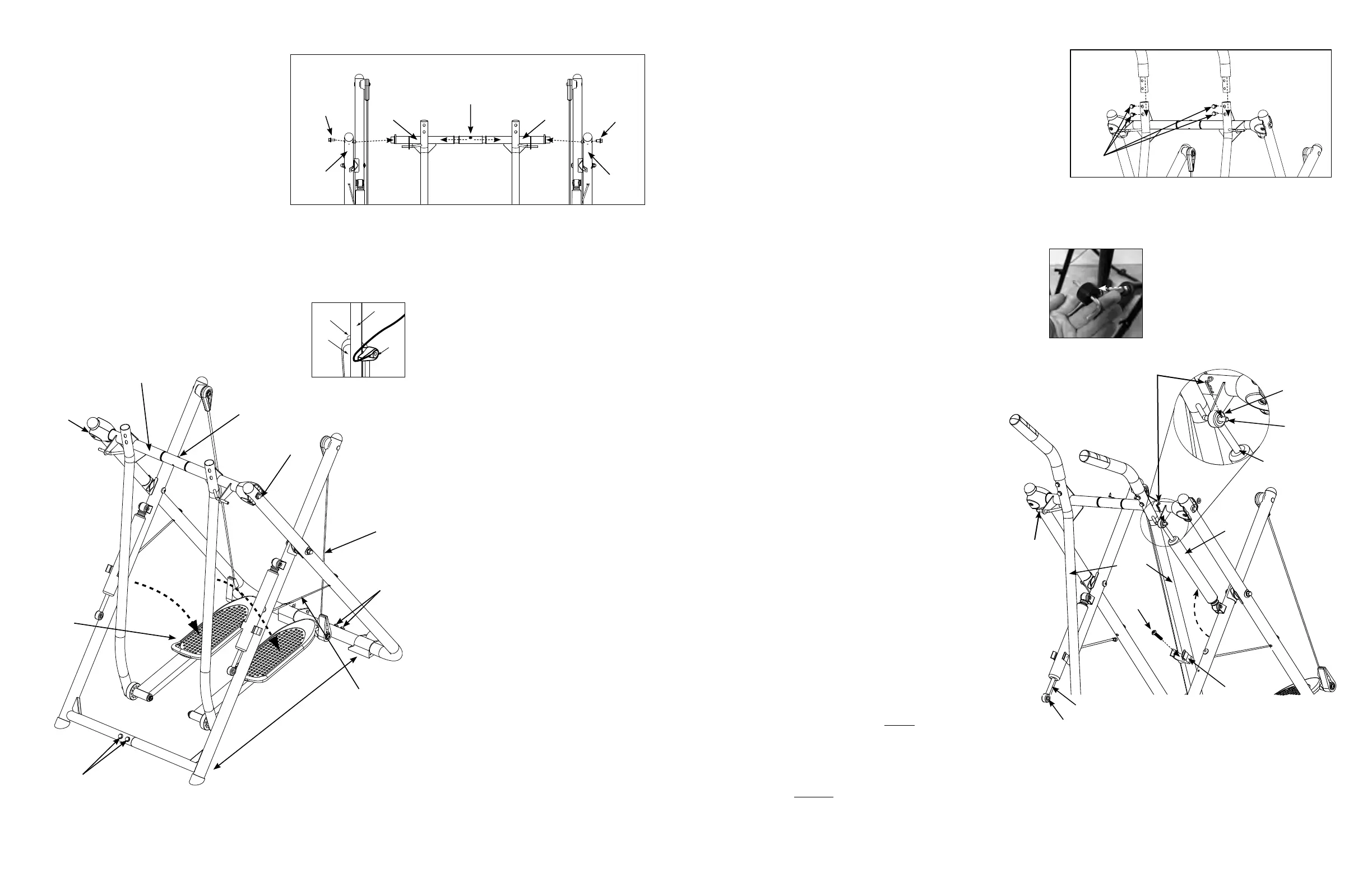
E. AXLE TUBE ASSEMBLY
1) Slide the axle tube through the left &
right swing arms & align axle tube to
properlytintoframes.Important –
the screw on the axle tube should be
angled facing up (as shown). This will
help will proper alignment of the
tness computer.
2) Insert bolts & washers into each frame
& axle tube end. Hand tighten only.
F. STAND THE UNIT UP
1) Lock the cable holders onto swing arms.
2) Stand the unit up as shown by lifting up
on the axle tube.
3) Spread the unit out & be sure frame
cables are tight.
4) Release the cable holders so the foot
platforms lower.
5) Be sure the swing cables hang straight
down, allowing the cables & swing arms
to move freely.
G. TIGHTEN BOLTS
1) Before tightening the axle tube,
make sure the screw in the center
of the axle tube faces angled up
(as shown). This will help for proper
alignmentofthetnesscomputer.
2) When tightening the axle tube, it may
be necessary to use both wrenches
simultaneously to tighten these bolts
securely.
3) Tighten front & rear frame bolts at the
bottom of the unit.
F5
swing cables
should hang
straight down
G3
G2
G2
F3
frame cables
should be tight
F3
spread
unit out
F2
lift from here
F4
lower foot
platforms
G3
Note: If you notice any gaps after
tightening, or extra space in the top
crossbar, use enclosed spare “C” washers.
Do not put “C” washers between center
sleeve & swing arms. (“C” washers can be
placed between swing arms & frames).
H. HANDGRIP ASSEMBLY
1) Remove the bolts & washers from each handgrip. Slide left
&righthandgripsintoswingarmsmakingsurethetness
computer wires face toward the center of the unit.
2) Line up holes & insert washers & bolts that were removed in
step H1. Tighten with the wrench provided.
TOP OF UNIT
E2
E2
left
frame
assembly
axle tube
right
swing
arm
left
swing
arm
right
frame
assembly
cable holders locked
onto swing arms
bumper
swing arm
cable
holder
foot
platform
F1
E1
E1
G1
H1
H1
H2
hydraulic
storage
clip
swing
arms
hydraulic
cylinder
phillips
bolt
eye
hook
safety pin
J3
J1
J5
inner rod
hook
eye
inner rod
J2
 Loading...