3
STANDARD INSTALLATION
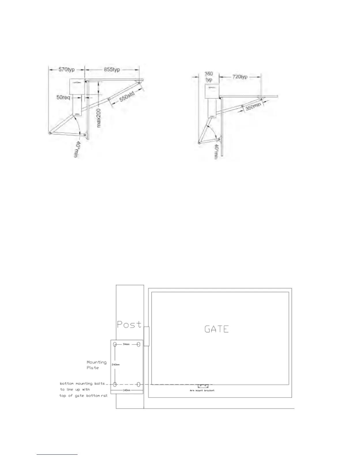
A standard installation is one where the gates open by swinging inward toward the operator. The gate hinge
should be no more than 200mm from the rear of the pillar or post and side room of 350mm is required to
accommodate the swing of the arms (see Figure 1)
Figure 1: Standard Installation * Restricted side room installation
1. Ensure that the gates swing freely and that all existing latches, drop bolts etc are disabled or removed.
2. The master operator (the one containing the circuit board) should be fitted to the gate pillar or post
nearest the power supply. Remove the covers from the operators to access the slotted fixing holes in the
rear of the chassis. Bend the tabs out and back against the rear of the chassis. In this position they act as
spacers allowing clearance for the cover.
3. Position each unit on the gate pillars or posts approximately 50mm from the edge of the pillar. The
vertical position is found by locating the gate bracket. This is best placed where there is adequate fixing
on the gate and movement of the arms is unrestricted (Figure 2). The units may now be bolted in place.
PLEASE NOTE: The chassis has laser cut tabs on the back (top and bottom) for standard mounting. These
tabs should be bent back. This eliminates the need to use spacers and ensures the chassis is spaced correctly
to ensure correct positioning of metal cover.
Figure 2: Position of Operator