Open Gate
Figure 8: Re-measure length of Secondary arm
4. Once the dimension is consistent, a new hole can be drilled in the Secondary arm and the arm trimmed to
suit. The gate bracket and Secondary arm should now be fitted.
OUTSWING INSTALLATION
In this type of installation the gate swings outward or away from the operators to the open position (Figure
6). Several factors must be considered to determine the most suitable arm length. These include the drive
through width required, the placement of the operators and the location of the gate. Direct support from the
supplier is always available in these situations.
NOTE: The polarity of the motor connections may need to be reversed on out-swing operation. See the
‘Overloads’ section.
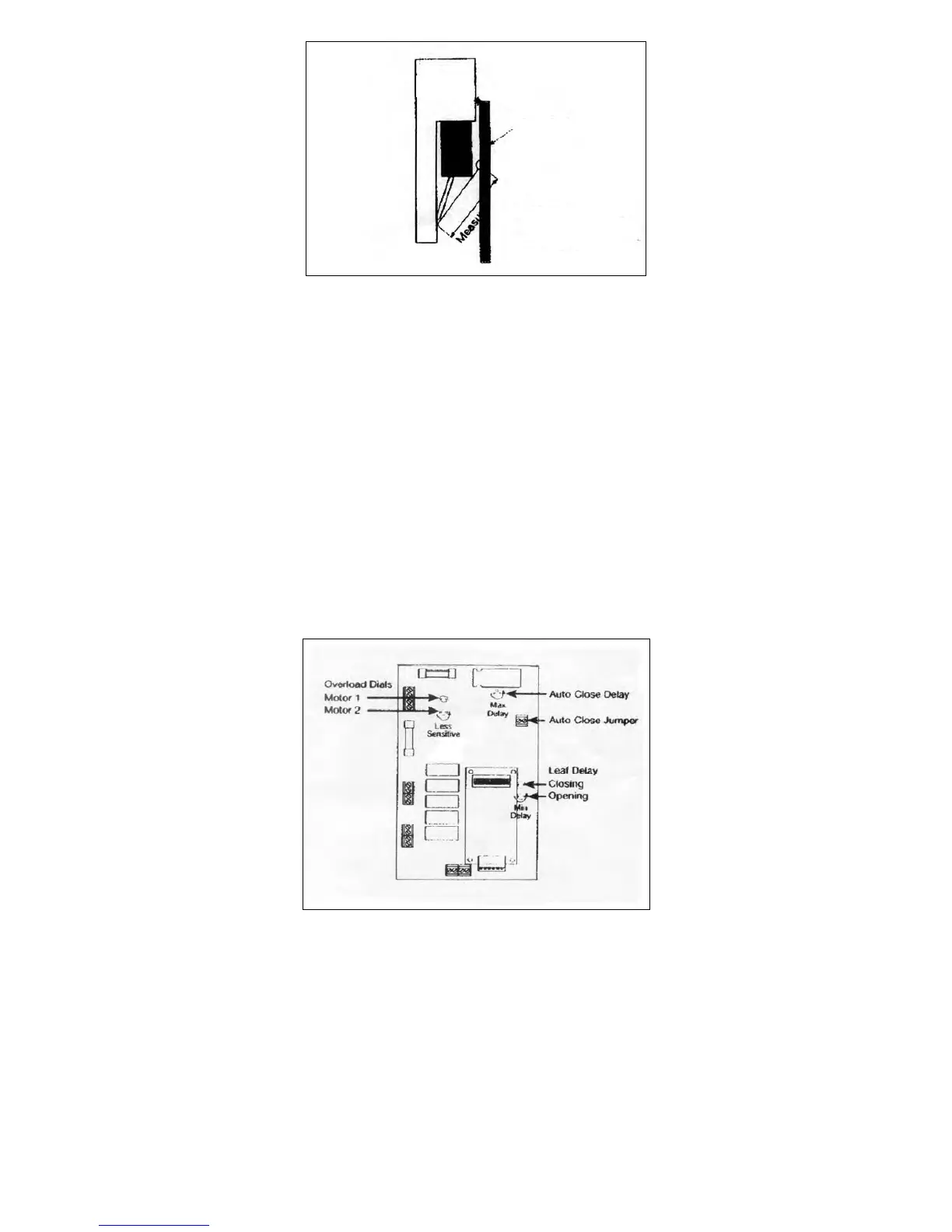
SETTINGS
AUTO CLOSE
The gates can be set to automatically close after a specific period.
This feature is activated by fitting a ‘jumper’ across the appropriate connection block (Figure 9) and
adjusting the Auto Close dial to the required time delay. Turning the dial anticlockwise increases the time
until the gates automatically close.
Figure 9: Settings
OVERLOAD
The overloads (Figure 9) are preset to maximum sensitivity i.e. slight pressure on the gate during operation
will cause the operator to stop if it is opening or stop and automatically reverse if it is closed.
NOTE: If these functions are reversed i.e. the gate stops when closing and stops and automatically reversed
when opening, then the polarity of the motor connections must be reversed, and the limit switch cams
adjusted.
There is one overload for each gate, as indicated on the circuit board. To reduce the sensitivity, turn the
overload dials in the anticlockwise direction.
Be Careful! Large reductions in sensitivity may allow the gates to exert excessive pressure on people or
vehicles trapped in the path of the gates.