SETPOINTS MODE - AUTORECLOSURE
5-50
selected. The PHASE INST LOSET and/or GROUND INST
LOSET trip feature can also be blocked after any reclosure
as selected.
The scheme will be reset to its initial condition if, after any of
the reclosures, the breaker closes and the current in all
phases is less than the PHASE O/C PICKUP setpoint for a
time greater than the reclosure SCHEME RESET time delay.
This is an improvement over the traditional “reclaim” time
since current sensing is used to ensure that the phase
current is below the pickup level. The scheme will also be
reset if the RESET key is pressed after a lockout condition
has been reached.
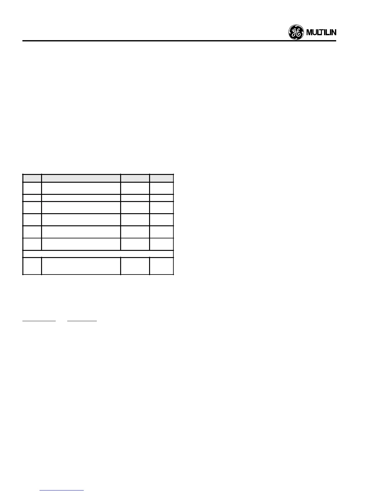
3. 575 Output Relays
The following 575 output relays are used by the reclosure
scheme:
NAME FUNCTION TERMINALS CONTACT
TRIP Trips C.B. 41 and 57
25 and 57
N/O
N/C
CLOSE Closes C.B. 42 and 58 N/O
AUX. 1 Operates with TRIP relay or is
programmable to alarm function.
43 and 59
46 and 59
N/O
N/C
AUX. 2 Programmable alarm function. 44 and 60
47 and 60
N/O
N/C
AUX. 3 Failsafe operation on loss of control
volts, and trip coil supervision.
45 and 61
48 and 61
N/C
N/O
AUX. 4 Operates on occurrence of Breaker
Discrepancy Alarm only.
30 and 31
32 and 31
N/O
N/C
BLOCK TAP CHANGER
Operates to block operation of external
transformer tap changer or can be used
as reclosure in progress indication.
16 and 15
29 and 15
N/O
N/C
4. 575 Input Terminals
The following inputs are required by the 575:
TERMINALS FUNCTION
9 and 10 Breaker auxiliary contacts (52b) must be wired
here. These contacts are closed when the
breaker is open.
11 and 10 Breaker auxiliary contacts (52a) must be wired
here. These contacts are open when the
breaker is open.
39 and 40 A LOCAL/REMOTE selector switch (43) should
be wired here. When these contacts are open
LOCAL mode is selected. When these con-
tacts are closed REMOTE mode is selected.
26 and 27 Remote Trip contacts can be wired here. A
contact closure here will cause the TRIP out-
put relay to activate for as long as the input
remains shorted.
28 and 27 Remote Close contacts can be wired here. A
contact closure here will cause the CLOSE
output relay to activate for as long as the input
remains shorted.
12 and 13 Remote Reclose Enable contacts can be wired
here. When REMOTE mode is selected a
contact closure here will cause the reclosure
scheme to be enabled. These contacts drive a
hardware latching relay in the 575 and can
therefore be momentary.
14 and 13 Remote Reclose Disable contacts can be wired
here. When remote mode is selected a con-
tact closure here will cause the reclosure
scheme to be disabled. These contacts drive
a hardware latching relay in the 575 and can
therefore be momentary.
Analog Input Trip and External Switch Trip
When either of these trips occur, the reclosure scheme will
immediately go to the lockout condition. The lockout is soft-
ware driven and not shown in hardware form on the
Autoreclose logic schematic.