70 MM300 MOTOR MANAGEMENT SYSTEM – COMMUNICATIONS GUIDE
FIELDBUS INTERFACE CHAPTER 1: COMMUNICATIONS GUIDE
Fieldbus interface
The Fieldbus interface is configurable as either Profibus DPV0/V1 or DeviceNet. Both
Fieldbus interfaces support control and status – refer to this MM300 Communications
Guide for map details.
Note that external power, 5 to 24 VDC, is required for this interface to operate. (Ensure that
switches 7 and 8 of the DIPswitch on the communication card, are ON.)
NOTE:
A GSD file is provided on the GE Multilin website: http://www.gedigitalenergy.com/app/
ViewFiles.aspx?prod=mm300&type=7
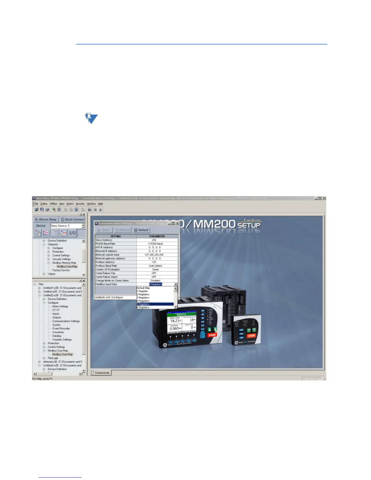
Configurable Fieldbus input data
The Input Data available to the Profibus master can be made user-configurable by using
the Modbus User Map feature available on the MM300.
Configure the setpoint Fieldbus Input Data available in the Communications Settings group
(Home > Setpnts > Cfg > Comms) page from the MM300 Graphical front panel if you have
ordered one with your unit).
By default this is set to use the default Profibus input data. Configure this to the number of
registers you want to read as part of Profibus Input Data. Configure this same number of
Modbus User Map registers to the required Actual value registers in the MM300 unit using
Enervista MM300/MM200 Setup. Save the Modbus User map configuration. These actual
values configured in User map are now available over Profibus.
 Loading...