CHAPTER 1: COMMUNICATIONS GUIDE FIELDBUS INTERFACE
MM300 MOTOR MANAGEMENT SYSTEM – COMMUNICATIONS GUIDE 75
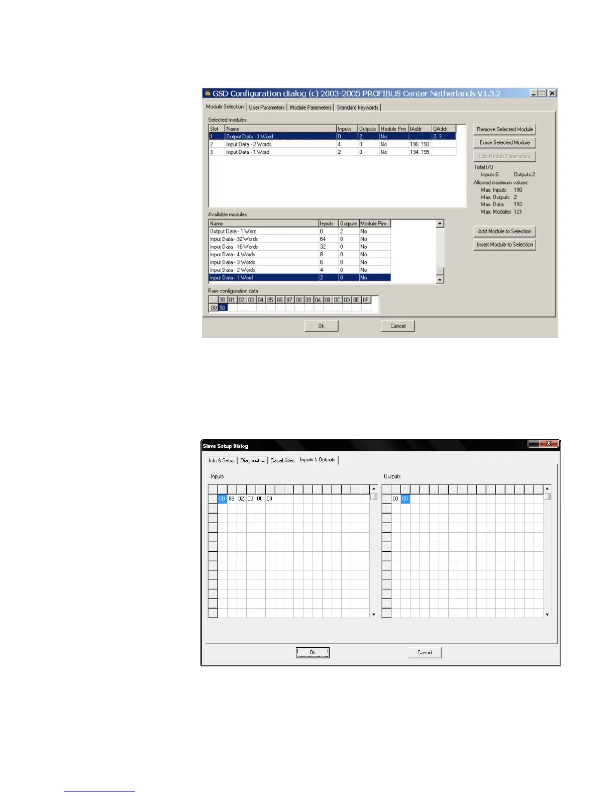
Figure 4: Profibus configuration menu
The diagram below shows the input and output data read from the MM300 with the
configuration above. When a size of input data smaller than the maximum is configured,
the data read from the MM300 by the master will start at address 0 of the Profibus Input
Data table (refer to section 4.1.4) and provide data in the order shown in that table, up to
the size configured. In this example, the data read via Input polling will consist of "Motor
Status", "Extended Status", and Thermal Cap. Used".
Figure 5: Profibus I/O data - 3 words in, 1 word out
 Loading...