Fan Installation
2.
3.
4.
5.
M
6.
N
B
L
B
Plug locking
pin
Mounting bracket
push lever
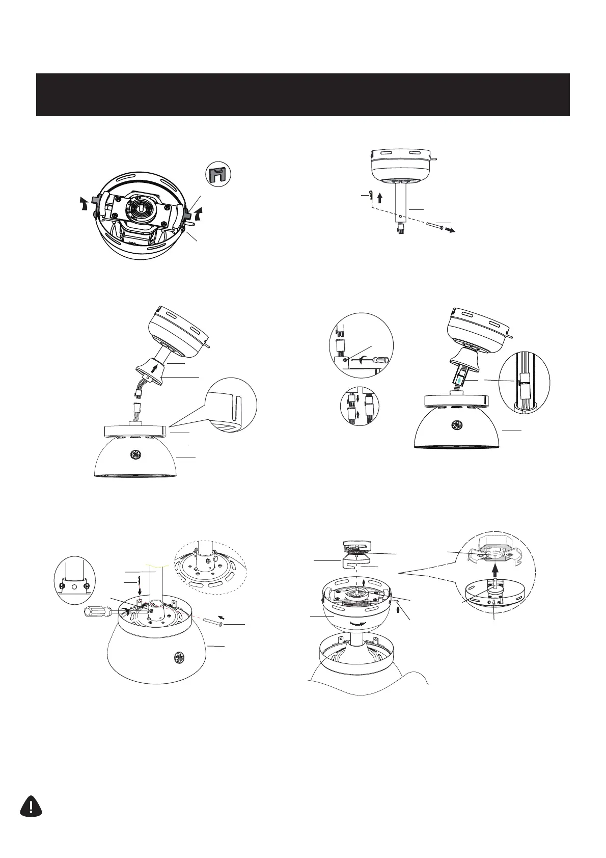
HANGING THE FAN
Remove the rubber insert located on the canopy
mounting screws (K) on both sides before installation.
1.
K
rubber insert
A
Locking pin
terminal
N
B
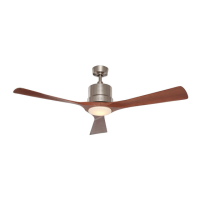
Remove the cotter pin (N) and clevis pin (M) from the
downrod of the canopy assembly (B).
Note: For installation and use of longer downrod
(option sold separately), instructions are available at
www.gelightingandfans.com
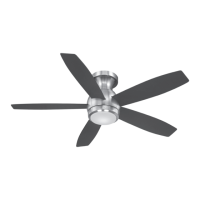
Place the canopy trim ring (C) on top of motor assembly (E)
and coupling cover (D) onto the downrod of the canopy
assembly (B).
B
D
C
E
,
To install the fan, raise the assembled fan housing up to the
ceiling receptacle (A). Press up on the push lever while lifting
the fan canopy (B) up to the receptacle (A) fully inserting the
fan plug locking pin into the receptacle locking pin terminal.
For correct alignment, make sure the mounting bracket
push lever on the canopy is placed in the middle between
the receptacle j slots as shown in the picture. Keep the
lever pushed up while turning the fan to the right (clockwise)
as shown in step 7.
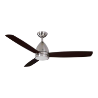
Loosen (but do not remove) the two collar set screws (L),
from the coupling on the top of the motor assembly (E).
Attach the 3-pin connectors from the downrod of the
canopy assembly (B) and motor assembly (E). Carefully
feed connectors into the downrod of the canopy
assembly (B).
3-pin connectors
L
B
E
WARNING: Failure to properly install cotter pin
could result in fan loosening and possibly falling.
Carefully insert the clevis pin (M) through the holes in the
collar and downrod (B). Be careful not to jam the clevis
pin (M) against the wiring inside the downrod (B).
Insert the cotter pin (N) through the hole near the end of
the clevis pin (M) until it snaps into its locked position.
Tighten two set screws (L) at top of the fan motor collar
firmly and evenly until fully engaged.
Align the holes at the bottom of the downrod (B) with the
holes in the collar on top of the fan motor assembly (E).
11
E
M
J slot