Fan Installation
9
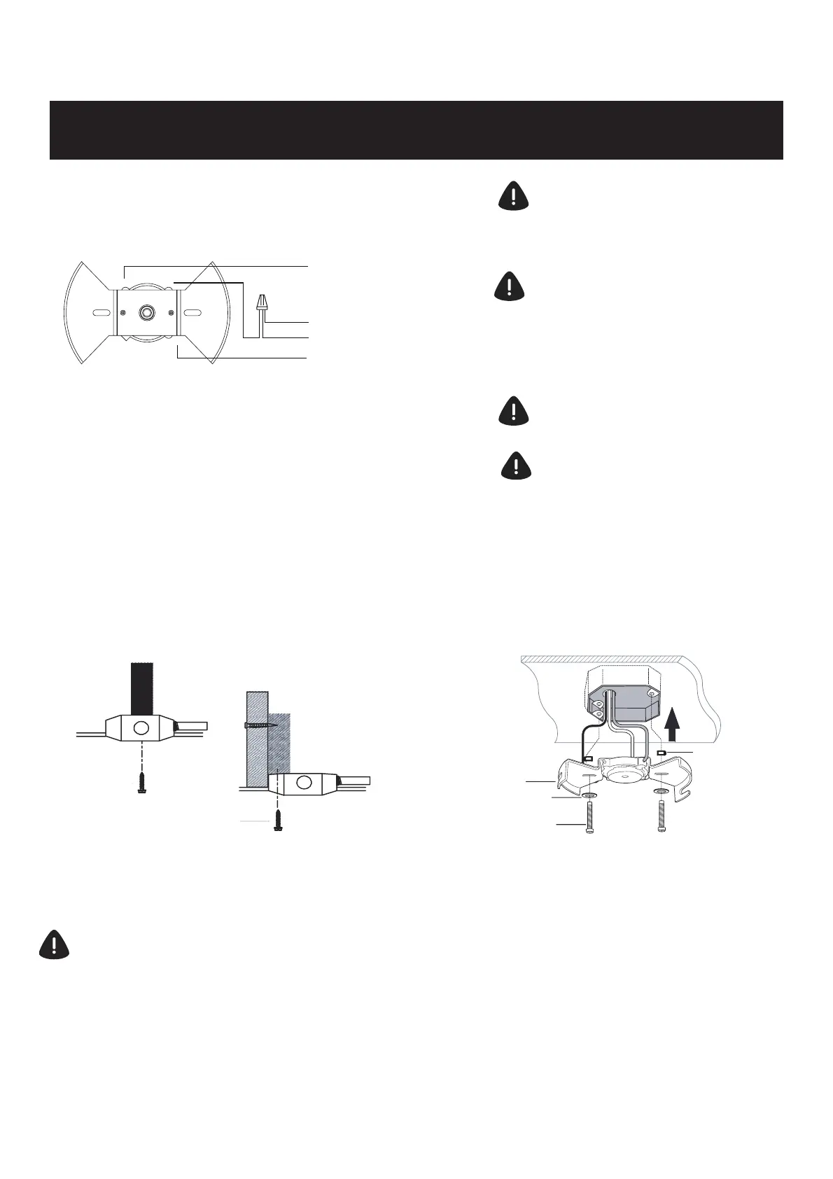
WIRING DIAGRAM 3:
Wiring Configuration with more than 1 of the same
the outlet box
white
green
black
(L1)
(L2)
W
G-ground
wire nut
white
When multiple wires are connected together, use a
solid wire 12-14 AWG jumper lead to insert into the
receptacle terminal.
WARNING: To avoid possible
electric shock, be sure electricity is
turned off at the main fuse box
before wiring.
NOTE: Fan must be installed at
a maximum distance of 6 m (20
ft.) from the transmitting unit for
proper signal transmission between
the transmitting unit and fan’s
receiving unit.
CAUTION : Do not use wall switch
with dimmer function.
WARNING : Do not use an existing
mounting bracket in the outlet box,
replace it with the powerplug
receptacle that is included with the
fan.
colored wires in
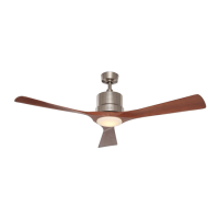
1.
Use metal outlet box (sold separately) suitable
for fan support. Secure outlet box directly to the
building structure using wood screws (AA). Outlet
box must support 15.9 kg (35 lb.) min.
DANGER: A loose outlet box can cause the
fan to wobble and increase the fan’s
potential to fall, which could result in
serious injury or death.
A
BB
CC
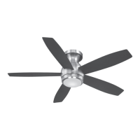
2.
Install powerplug receptacle (A) to outlet box
using the mounting screws (with lock washer)
(BB) and flat washers (CC) provided with the
outlet box. (Two additional mounting screws
(with lock washer) (BB) and flat washers (CC)
are provided in the hardware bag).
Rubber Washer
The placement of the powerplug
receptacle on the ceiling is important for the
fan plug to make the correct installation and
securement. The powerplug should be evenly
flush with the ceiling. Use the rubber washers
as shown in the figures on next page.
NOTE:
AA
INSTALLING THE POWERPLUG RECEPTACLE
View Installation Video@
www.gelightingandfans.com
NOTE: Be sure to push each wire from ceiling all the
way into corresponding terminal on powerplug
receptacle. If wire is not inserted completely, there is a
possibility that the electrical connection will fail. If you
have multiple wires connected together, add a jumper
lead and insert jumper lead into terminal. One single
wire is inserted into terminal.