9
ASSEMBLING THE ANTENNA:
1) Connecting the VHF Dipole
a) Remove the foam block covering the bolts and nuts from the
antenna Main Boom.
b) Remove the nuts and lock washers from the bolts.
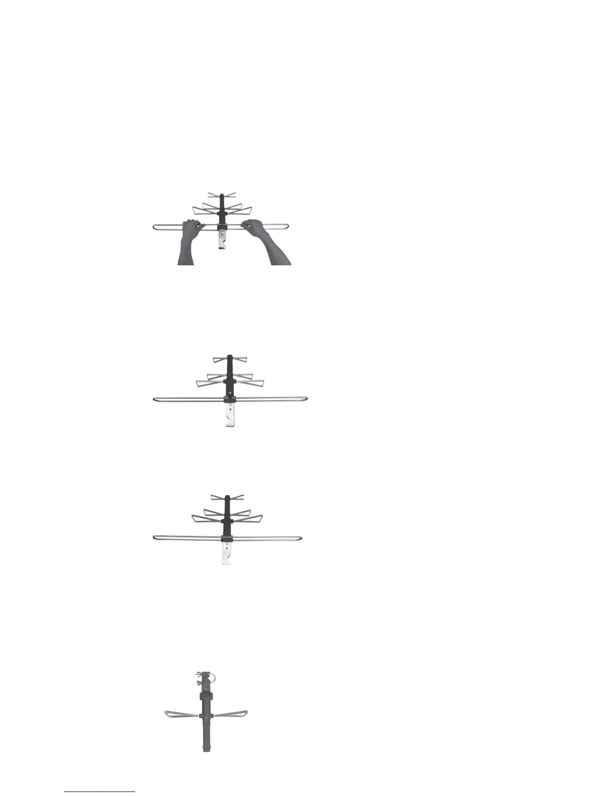
c) Connect together the two halves of the VHF Dipoles, one end is
tapered to slide into the other half as illustrated in (Fig. 1a).
Fig. 1a
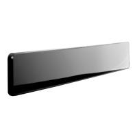
d) Connect the VHF Dipoles onto the antenna Main Boom and slide
the two open ends over the protruding bolts from the antenna
Main Boom. Secure with the two tooth washers and nuts
previously removed. Do not overtighten the nuts onto the bolts
(Fig. 1b).
Fig. 1b
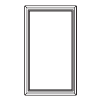
e) Using the M3 X 14mm Sheet Metal Screw, secure the other
side of the VHF Dipole to the antenna Main Boom (Fig. 1c).
Fig. 1c
2) Connecting the UHF Dipoles: (Part Labeled “C,” “B” and “A”)
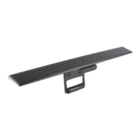
a) On the antenna Main Boom, you will see the letter “C” embossed
on the boom; attach the Dipoles labeled “C” to the Main Boom
using the two M3 X 12mm Bolts and Nuts. (The “C” from the
Dipoles should be facing up.) Do not overtighten the bolts (Fig. 2a).
Fig. 2a


 To Next Page