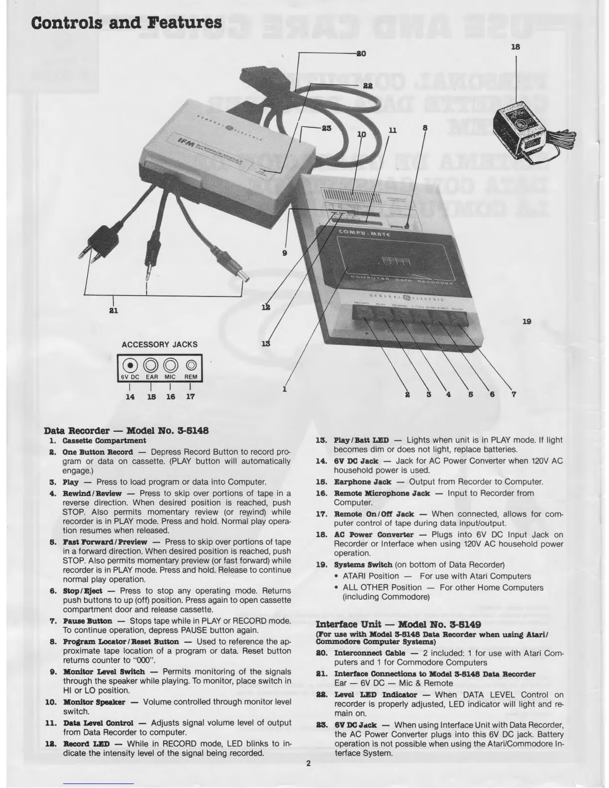
Controls and Features
ACCESSORY JACKS
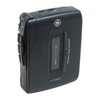
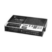
Data Recorder — Model No. 3-5148
1. Cassette Compartment
8. One Button Record — Depress Record Button to record pro
gram or data on cassette. (PLAY button will automatically
engage.)
3. Play — Press to load program or data into Computer.
4. Rewind/Review — Press to skip over portions of tape in a
reverse direction. When desired position is reached, push
STOP. Also permits momentary review (or rewind) while
recorder is in PLAY mode. Press and hold. Normal play opera
tion resumes when released.
5. rast Forward/Preview — Press to skip over portions of tape
in a forward direction. When desired position is reached, push
STOP. Also permits momentary preview (or fast forward) while
recorder is in PLAY mode. Press and hold. Release to continue
normal play operation.
6. Stop/Eject — Press to stop any operating mode. Returns
push buttons to up (off) position. Press again to open cassette
compartment door and release cassette.
7. Pause Button — Stops tape while in PLAY or RECORD mode.
To continue operation, depress PAUSE button again.
8. Program Locator / Reset Button — Used to reference the ap
proximate tape location of a program or data. Reset button
returns counter to “000".
9. Monitor Level Switch — Permits monitoring of the signals
through the speaker while playing. To monitor, place switch in
HI or LO position.
10. Monitor Speaker — Volume controlled through m onitor level
switch.
11. Data Level Control — Adjusts signal volume level of output
from Data Recorder to computer.
18. Record LED — While in RECORD mode, LED blinks to in
dicate the intensity level of the signal being recorded.
13. Play/Batt LED — Lights when unit is in PLAY mode. If light
becomes dim or does not light, replace batteries.
14. 6V DC Jack — Jack for AC Power Converter when 120V AC
household power is used.
18. Earphone Jack — Output from Recorder to Computer.
16. Remote Microphone Jack — Input to Recorder from
Computer.
17. Remote On/Off Jack — When connected, allows for com
puter control of tape during data input/output.
18. AC Power Converter — Plugs into 6V DC Input Jack on
Recorder or Interface when using 120V AC household power
operation.
19. Systems Switch (on bottom of Data Recorder)
• ATARI Position — For use with Atari Computers
• ALL OTHER Position — For other Home Computers
(including Commodore)
Interface Unit — Model No. 3-5149
(Tor use with Model 3-8148 Data Recorder when using Atari/
Commodore Computer Systems)
80. Interconnect Cable — 2 included: 1 for use with Atari Com
puters and 1 for Commodore Computers
81. Interface Connections to Model 3-8148 Data Recorder
Ear — 6V DC — Mic & Remote
88. Level LED Indicator — When DATA LEVEL Control on
recorder is properly adjusted, LED indicator will light and re
main on.
83. 6V DC Jack — When using Interface Unit with Data Recorder,
the AC Power Converter plugs into this 6V DC jack. Battery
operation is not possible when using the Atari/Commodore In
terface System.