EasyManua.ls Logo

GE ACR11B - Page 8

GE ACR11B
23 pages
Print Icon
To Next Page IconTo Next Page
To Previous Page IconTo Previous Page
Loading...
GEH-~786
Recl68lng Relay Type ACR
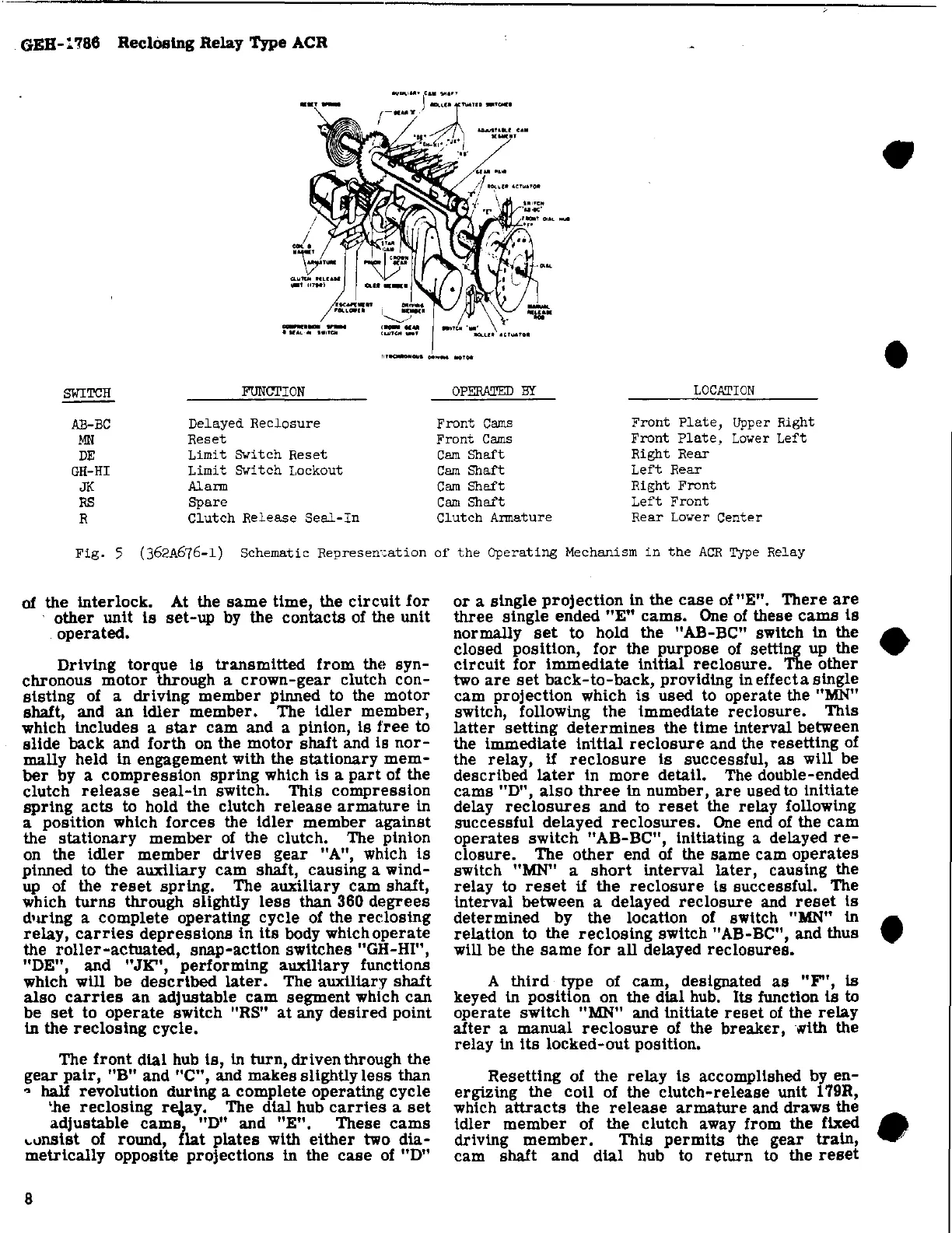
SWITCH
FUNCTION
OPERATED
BY
LOCATION
AE-BC
Delayed
Reclosure
Front
Cams
Front
Plate,
Upper
Right
MN
Reset
Front
Cams
Front
Plate,
Lower
Left
DE
Limit
Switch
Reset
Cam
Shaft
Right
Rear
GH-HI
Limit
Switch
Lockout
CamShaft
Left
Rear
JK
Alarm
Cam
Shaft
Right
Front
RS
Spare
Cam
Shaft
Left
Front
R
Clutch
Release
Seal-In
Clutch
Armature
Rear
Lover
Center
Fig.
5
(362A676-l)
Schematic
Represen-cation
of
the
Operating
Mechanism
in
the
ACR
Type
Relay
of
the Interlock. At the
same
time,
the
circuit
for
other
unit
is
set-up
by
the
contacts
of the
unit
operated.
Driving
torque
is
transmitted
from
the
syn-
chronous
motor
through a
crown-gear
clutch
con-
sisting
of a
driving
member
pinned to the
motor
shalt,
and
an
idler
member.
The
idler
member,
which Includes a
star
cam
and a pinion,
is
free
to
slide
back
and
forth
on the
motor
shalt
and
is
nor-
mally held In engagement with the
stationary
mem-
ber
by a
compression
spring
which
is
a
part
of the
clutch
release
seal-in
switch.
This
compression
spring
acts
to hold the clutch
release
armature
in
a
position
which
forces
the
idler
member
against
the
stationary
member
of the clutch. The pinion
on the
idler
member
drives
gear
"A", which
is
pinned to the
auxiliary
cam
shalt,
causing
a wind-
up of the
reset
spring.
The
auxiliary
cam
shalt,
which
turns
through slightly
less
than 360
degrees
d'll"ing a
complete
operating
cycle
of the
redosing
relay,
carries
depressions
in
its
body which
operate
the
roller-actuated,
snap-action
switches
"GH-HI",
"DE",
and
"JK"
,
performing
auxiliary
functions
which will
be
described
later.
The
auxiliary
shalt
also
carries
an
adjustable
cam
segment
which
can
be
set
to
operate
switch "RS"
at
any
desired
point
in
the
reclosing
cycle.
The
front
dial
hub
is,
In
turn,
driven
through
the
gear
pair,
"B"
and
"C",
and
makes
slightly
less
than
•
half
revolution
during
a complete operating
cycle
'lie
reclosing
r$Y.
The dial hub
carries
a
set
adjustable
cams,
"D" and
"E".
These
cams
""nsist
of round,
flat
plates
with
either
two
dia-
metrically
opposite
projections
in the
case
of
"D"
8
or
a
single
proj
ection
in the
case
of
"E".
There
are
three
single
ended
"E"
cams.
One of these
cams
is
normally
set
to hold the
"AB-Be"
switch in the
closed
position,
for
the
purpose
of setting up the
circuit
for
immedlate
Initlal
reclosure.
The
other
two
are
set
back-to-back,
providing in effect a
single
cam
projection
which
is
used to operate the "MN"
switch, following
the
immediate
reclosure.
This
latter
setting
determines
the
time
Interval between
the
immedlate
initial
reclosure
and the
~esetiing
of
the
relay,
if
reclosure
is
successful,
as
will be
described
later
in
more
detail. The double-ended
cams
"D",
also
three
In
number,
are
used to
initiate
delay
reclosures
and
to
reset
the
relay
following
successful
delayed
reclosures.
One
end of the
cam
operates
switch
"AB-Be",
initiating a delayed
re-
closure.
The
other
end
of
the
same
cam
operates
switch "MN" a
short
interval
later,
causing the
relay
to
reset
if
the
reclosure
is
successful. The
Interval between a delayed
reclosure
and
reset
Is
determined
by
the
location of switch "MN" in
relation
to
the
reclosing
switch
nAB-Be",
and thus
will be the
same
for
all
delayed
reclosures.
A
third
type of
cam,
designated
as
"F",
is
keyed
In
position
on the dial hub. Its function
is
to
operate
switch
"MN" and
initiate
reset
of
the
reiay
after
a manual
reclosure
of
the
breaker,
with the
relay
in
its
locked-out
position.
Resetting
of
the
relay
is
accomplished by
en-
ergizing
the
coil
of the
clutch-release
unit 179R,
which
attracts
the
release
armature
and
draws
the
idler
member
of the clutch away from the fixed
driving
member.
This
permits
the
gear
train,
cam
shalt
and
dial
hub to
return
to the
reset
•
•
•
•
•