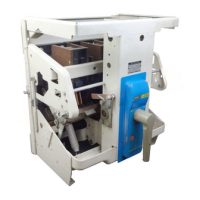
REVERSE
CURRENT TRIPPI
NG
DEVICE
AK-50
ONLY
(Fig.
31}
The device
is
enclosed in a molded
case
and
is
mounted on the
right
pole
base
simila
.r to the.
series
overcurrent
tripping device.
The
reverse
-
current
tripping device
(see
Fig.
28}
consists
of a
se
ries
co
il
(2}
with an
iron
core
mount-
ed between two pole
pieces
(9),
also
a potential
coil
(7)
connected
across
a constant
source
of
voltage and mounted around a rot;ary·-type
arm-
ature
(10). Calibration
spring
(6)
determines
the
armature
pick-up when a
reversal
of
current
occurs.
As long
as
the flow of
~urrent
throug_h
the
breaker
is
in
the normal direction, the magnetic flux
of the
series
coil
and the magnetic
flux
of the
potential
coil
produce a torque which tends to
rotate
the
armature
counterclockwise. The calib-
ration
spring
also
tends to rotate the
armature
in
the
same
direction
. This torque
causes
the
armature
to
rest
against the stop
screw
(12)
attached to a
bearing
plate on the
right
side
of the
device.
If the
current
through the
series
coil
(2)
is
reversed,
the
armature
(10)
tends to move in the
clockwise
direction
against the
restraint
of the
calibration
spring
(6). When the
current
reversal
exceeds the calibration setting, the
armature
-
revolves
clockwise causing the
trip
rod
(3)
to
move upwa.
rd
engaging the
trip
paddle (1),
there-
by
tripping
the
breaker.
AD
JU
ST
ME
NT
S
(Fig.
31)
The
only adjustment to be made on the
rev
er~e
curr
ent
device
is
-to make
sure
that
the
trip
rod
has
a minimum
overtravel
of 1/32 in. beyond
the
point of tripping the
breaker.
Th
is
adjus!me~t
should have
to
be made only when an old device
is
bei_ng
rep~aced by a new one.
·
The
new device will be factory adjusted so that
the top end of the
trip
.
rod
(3)
will-extend 1/2
-
in.
above
the
top of the device
case,
and
no
addi-
tional adjust.ments of the
trip
rod
should be
required.
To
obtain the
proper
1
/32
in.
over-
travel,
cl~se
the
break~r
~d
proceed
as
follows:
1.
Loosen
the locking nut (2B).
2. Manually
lift
the
trip
rod
and
vary
the
. position of
the
adjusting nut (2A}, this establish-
ing the
position
of the adjusting nut where the
breaker
is
just
tripped
.
NOTE:
Be
sure
to
keep
clear
of moving
breaker
parts
when tripping the
breaker.
3.
With
this
position of the adjusting nut
established,
advance the adjusting nut upward
one
and
one-half
turns
.
4. Tighten the locking nut and the mfnimum
1
/3
2-in
.
overtravel
of the
trip
rod
should be
obtained.
Low Voltage Power
Circuit
Breakers
GEK-7303
R
EPLA
CE
M
EN
T (Fig. 31)
After
removing the wiring for the potential
coil the
rever
se
current
device can
be
rem
oved
and
replaced
by following the
procedure
outlined
for
replacing
the
serie
s
overcurrent
device.
For
wiring,
see
Fig.
31).
POWER
SENSOR
T
RIP
GENERAL
DESCRIPTION
All AK-3 Type
Air
Circuit
Breakers
contain
Power
Sensor
Overcurrent
Trip
Devices.
The
Power
Sensor
Trip
functions with
solid
state
components .with the exception of the Solenoid
Trip
which
is
used
to
trip
the
breaker
on signal
from
the
Power
Sensor Unit. The
Power
Sensor
Overcurrent
Trip
Device
consists
of four
major
components.
1.
The
magnetic
coils
around the
breaker
conductors (Fig.
32
& 33).
2. The Power Supply which provides both
the tripping energy and the
comparison
basis
for
overcurrent
detection (Fig. 34). ·
3.
The Power Sensor Unit with the
various
pick-up
settings and
time
delay
selection
taps
(Fig.
35}.
-
4.
The
trip
solenoid which physically
trips
the
breaker
(Fig.
36}.
In addition to the phase overcu_
rrent
protection,
a ground fault sensing
feature
may be provided.
The Ground Sensing Devi
ce
works on the principle
that
the instantaneous value of
cur
rent
flowing in
the
three
conductors (or; in four condu_
ctors
on
four
wire
sys
tems)
must add to
zero
unless
gro_und
current
is
flowing. ~
Therefore,
if
the electrical
system
is
a four wire wye
system
with the neut~al
grounded
at
the
transformer,
the fourth sensing
coil
Fig.
38 must be included on the neutral
conductor with
its
secondary combined with the
secondaries
of
the
three
phase
sensors
which
are
mounted on the
breaker.
On
Draw-out
breakers
the output of the external
neutral
sensor
must
enter
the
breaker
by a control disconnect which
is
mounted low and
on
the centerline
on
the back of
the
breaker.
Refer to
Fi
g.
(37)
for Ppwer Sensor
Cabling Diagram.
MAINTENANCE
When mal-functioning of thePower Sensor
Trip
is
indicated, the trouble should be
traced
to
one
or
more
of
these
four components involved, and
that
component should be replaced
as
a unit.
The
following
steps
should be taken to detect a
mal-
functioning unit. .-
NOTE:
No
adjustment to· the taps controlling
pi
ck-up should be made with the
breaker
car
-
rying
current
.
In
the event the Power Sensor Devi
ce
must
be made non-operative to allow the
breaker
to

 Loading...


