GEK-721 01,
Low
V
oltage
Swifchgeor
SECONDARY
DISCONNECTS
INNER HOUSE
PADLOCK
DEVICE
INDICATOR
STOP
LINK
KEY INTERLOCK
DRAWOUT
MECHANISM
PIN
KEY
INTERLOCK SLIDE
TRACK LOCK LINK
CURRENT
TRANSFORMER
ROLLOUT TRACK
GROUND SENSOR
SECONDARY
DISCONNEC
POSITION SWITCH
AND COVER
COVER
REQ'D.
IN FUSED
BRKR. COMPT. ONLY
AMMETER
SWITCH
AMMETER
ULUJE
FUSES
INDICATING
LIGHTS
TEST
SWITCHES
TRIP
FUSES
{
ooon
-
INTERLOCK
iir
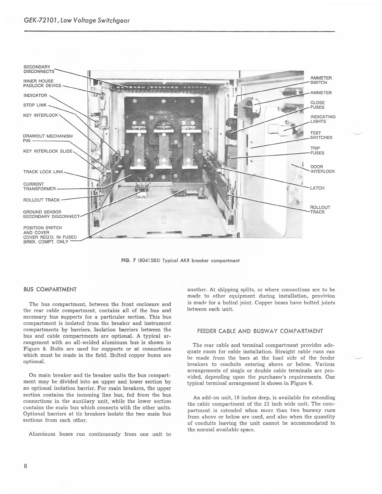
FlG.
7
(8041
585) Typicol AKR
breoker comportmenl
BUS
COMPARTMENT
The
bus compartment,
between
the
front enclosure
and
the rear
cable compartment, contains
all
of the bus and
necessary bus supports for
a
particular
section.
This
bus
compartment
is isolated from the
breaker
and instrument
compartments
by barriers. Isolation barriers between the
bus and cable compartments are optional. A typical ar-
rangement with an all-welded
aluminum bus
is shown in
Figure
8. Bolts are used for supports or at connections
which must be made in the field. Bolted copper buses are
optional.
On main breaker and tie
breaker units the bus compart-
ment may be
divided into an upper and lower section
by
an optional isolation
barrier. For main
breakers,
the
upper
section contains
the
incoming
line bus, fed from
the
bus
connections in the auxiliary unit,
while
the lower section
contains
the
main
bus which connects with the other units.
Optional
barriers at tie breakers isolate the two main bus
sections
from each other.
Aluminum buses run
continuouslv from one
unit to
another.
At shipping splits,
or where connections
are to be
made to other equipment
during installation,
provision
is mad" for
a bolted
joint.
Copper buses have bolted
joints
between each
unit.
FEEDER
CABLE AND BUSWAY COMPARTMENT
The
rear cable and terminal compartment
provides
ade-
quate
room for cable installation. Straight cable runs can
be made from the bars
at
the load side of the feeder
breakers to
conduits entering above or below. Various
arrangements
of
single
or double cable terminals are
pro-
vided,
depending upon the
purchaser's
requirements. One
typical terminal arrangement is
shown
in Figure
9,
An add-on unit, 18 inches deep, is
available
for extending
the cable compartment of
the 22 inch wide unit. The com-
partment
is
extended when
more than
two
busway runs
from above
or
below are used, and
also when tlre
quantity
of conduits leaving the
unit
cannot be
accommodated in
the normal available space.
 Loading...