Do you have a question about the GE AKD-8 and is the answer not in the manual?
Outlines inspection upon receipt, damage reporting, and careful handling procedures for the operator.
Specifies ideal storage environments and conditions to protect the remote racking operator.
Explains the drive train, control switches, and attachment brackets for small frame AKR breakers.
Details modifications needed for AKR 30/50 and 30s breakers before attaching the operator.
Step-by-step guide for physically connecting the remote racking operator to the breaker.
Instructions for installing the mounting bracket kit on AKR 30S breakers.
Instructions for installing the mounting bracket kit on AKR 30/50 breakers.
Details the drive train, control switches, and attachment brackets for large frame AKR breakers.
Guide for connecting and disconnecting the remote racking operator from large frame AKR breakers.
Illustrates drilling steps for modifying AKR 30S, 75/100, and 125 breaker doors.
Illustrates drilling steps for modifying AKR 30/50 breaker doors.
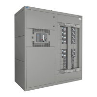
The GE Energy Industrial Solutions Low Voltage Switchgear Remote Racking Operator is a portable device designed to safely move drawout circuit breakers between CONNECT, TEST, and DISCONNECT positions within AKD-8 Switchgear. This operation is performed remotely, enhancing operator safety by keeping them away from the energized equipment during racking procedures. The device is specifically designed for AKR Circuit Breakers and requires 115 VAC, 50/60 Hertz control power.
The primary function of the remote racking operator is to automate the manual racking process of AKR circuit breakers. It consists of a drive train, control switches, and attachment brackets. The drive train includes a gear motor housing and a square drive coupler that connects to the breaker's drawout mechanism. This allows the motor to turn the racking screw, moving the breaker in or out of its cubicle.
Control of the racking operation is managed through a hand-held control box connected to the operator via a thirty-foot cable, enabling remote operation. The control box features a spring-loaded start switch, which requires continuous pressure to keep the motor running. This safety feature ensures that the operator maintains active control throughout the racking process. A directional toggle switch, mounted on the motor housing, allows the operator to select "IN" for racking toward the CONNECT position or "OUT" for racking toward the DISCONNECT position.
A key safety mechanism is the device's ability to sense motor stall current. When the breaker reaches the end of its travel (either fully connected or fully disconnected), the motor stalls, causing a higher motor stall current. This current surge trips an integrated circuit breaker to the OFF position, automatically cutting power to the motor and preventing over-racking or damage to the breaker or switchgear.
The remote racking operator is designed for ease of attachment and removal from AKR circuit breakers. Before attachment, the circuit breaker must be in the OPEN position. For AKR 30/50 breakers, the racking screw cover on the breaker escutcheon needs to be slid to the right, and the remote racking attachment cover on the cubicle door slid to the left to expose an opening. For AKR 30S breakers, either the upper or lower racking screw access cover on the cubicle door is slid to the left, revealing two openings.
The operator is positioned so that its square drive coupling aligns with the breaker's square racking shaft, and a ¼-turn latch rod engages the breaker frame. If alignment is not immediate, the motor shaft extension on the back of the motor housing can be rotated to achieve proper engagement. Once aligned, the operator is pushed toward the breaker, and the ¼-turn latch rod is rotated counter-clockwise to lock it securely to the breaker. A visual check ensures the latch is fully engaged with the breaker front cover.
Removal is a reverse process: the latch release on the left side of the operator is rotated clockwise, allowing the operator to be pulled away from the breaker. The racking screw access covers on the cubicle door will automatically close upon removal.
The device requires specific mounting brackets to be added to existing AKR 30/50 and AKR 30S breakers before initial use. For AKR 30S breakers, a mounting bracket is installed on the right side, just above the racking screw. For AKR 30/50 breakers, a bracket is added to the left side of the escutcheon on the breaker frame. These modifications ensure proper attachment and operation.
Field modifications to existing breaker doors are also necessary to accommodate the remote racking operator. Drilling templates are provided to create the necessary access holes in the cubicle doors for both small and large frame AKR breakers. This ensures that the operator can be properly mounted and its components can interface correctly with the breaker.
The manual emphasizes the importance of inspecting the remote racking operator upon receipt for any transit damage. Any damage or signs of rough handling should be reported immediately to the transportation company and the GE Distributor. When unpacking, care should be taken to locate all "loose parts" such as couplers, mounting brackets, and support plates, which are essential for proper assembly and operation.
For long-term storage, the device should be protected from condensation and stored in a warm, dry environment with moderate temperatures (40°F to 100°F) and free from corrosive gases. Prior to use after any period of storage, a thorough inspection is recommended to ensure its proper mechanical and electrical working condition.
As part of the installation process, the existing racking screw mechanism on the breaker needs to be inspected for excessive wear and properly lubricated. This proactive maintenance ensures the smooth operation of the racking mechanism and prolongs the life of both the breaker and the remote racking operator. The installation instructions for mounting brackets include specific torque values for bolts, highlighting the importance of correct assembly to prevent improper alignment and potential damage.
| Current Rating | 8A |
|---|---|
| Number of Poles | 3 |
| Frame Size | AK |
| Current Range | 8A |
| Enclosure | Molded Case |