Do you have a question about the GE A-Series II Panelboard and is the answer not in the manual?
Remove all power from the panelboard before attempting installation.
Remove interior assembly, dead front, and circuit breaker kit from packaging and verify parts.
Mount branch bases for A phase adjacent to cross bar and secure with screw [7].
Mount branch bases for B and C phases to main busbar, adjacent to other bases, using screws [7].
Refer to Figure 2 for mounting the breaker on the left side of the interior.
Mount the bracket [8] on the interior rail with screws [9] with specified torque.
Secure spools [4] to the underside of the breaker terminal using screws [5] and conical washer [6].
Place breaker over branch bases, align spool, and tighten screws [5] to branch bases.
Insert screws [14] into the circuit breaker and tighten to bracket [8] with specified torque.
Remove four screws [12] of the existing filler plate from the dead front.
Install filler plate [11] over dead front on left side, align holes, and fasten with screws [12].
Install filler plate [11] over dead front on right side, align holes, and fasten with screws [12].
Reattach the dead front to the interior with the 8 screws removed in step 2.
Install SF breaker after SG, following gap specifications and replacing blank filler with SF filler plate.
Install SF breaker after crossbar, ensuring a 0.061-inch gap between breaker and crossbar.
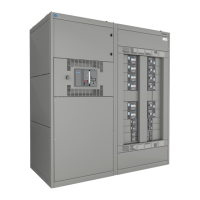
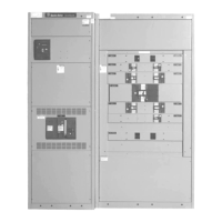
This document outlines the installation procedures for SF three-phase circuit breaker kits into A-Series® II panelboards, specifically for AD/AE/AQ Type P & N Power Panels. These kits are designed for use in panelboards that were originally ordered with un-specified space, providing a flexible solution for expanding or customizing electrical configurations. The primary function of these kits is to integrate SF three-phase circuit breakers, which are essential components for protecting electrical circuits from overcurrents and short circuits, into existing panelboard systems.
The installation process is detailed step-by-step, ensuring that the circuit breaker kit is correctly and safely integrated. A critical safety warning emphasizes the necessity of removing all power from the panelboard before any installation attempt, highlighting the importance of electrical safety during maintenance and installation.
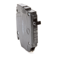
The kit itself, identified by the catalog number ASPP6SF3S, includes a comprehensive set of parts required for a complete installation. These parts include:
The installation begins with the preparation of the panelboard interior. This involves removing the interior assembly from its packaging and verifying all parts against the provided list. Subsequently, the dead front of the panelboard needs to be removed by unscrewing the securing screws (8 screws for 600A and 800A panels), which are then set aside. This step grants access to the panelboard's internal components where the circuit breaker will be installed.
The core of the installation involves mounting the circuit breaker on either the left or right side of the interior, depending on the specific configuration required. The instructions provide detailed guidance for both scenarios. For mounting on the left side, the branch base for the A phase is placed adjacent to the crossbar, and a screw is inserted through the provided slot to clamp it with the main busbar. This process is repeated for the B and C phase branch bases, ensuring they are adjacent to each other and clamped to their respective main busbars. All phase branch bases must be securely clamped with screws, tightened to a specified torque of 60 in-lb maximum.
A similar procedure is followed for mounting the breaker on the right side, with the same emphasis on correctly positioning and clamping the branch bases to the main busbars, but with a slightly adjusted torque range of 50-70 in-lb for the screws. This flexibility in mounting options allows for adaptable panelboard layouts.
Further steps involve mounting a bracket onto the interior rail using two screws, tightened to 27-36 in-lb, at a defined location. This bracket provides additional support for the circuit breaker. The conical washers are then placed over the screws, which are inserted through the holes in the top of the circuit breaker. The spools are secured to the underside of the breaker terminal with these screws, ensuring the tapped end of the spool faces the breaker terminal. This careful assembly ensures a robust and secure connection.
Once the breaker is positioned over the branch bases, the spools are aligned with the protruded openings in the branch bases, and the screws are tightened to 60 in-lb maximum. Two additional screws are inserted into the circuit breaker and tightened to the bracket with 18-22 in-lb, further securing the breaker in place.
The document also addresses the aesthetic and safety aspects of the installation by detailing the process of preparing the dead front. This involves removing existing filler plate screws from the dead front where the SF breaker is to be installed. A new filler plate, provided with the kit, is then placed over the dead front, aligning its holes with the threaded holes of the dead front. This filler plate is fastened with four screws, tightened to 27-36 in-lb. If the breaker is installed on the right side, the filler plate is simply flipped to ensure proper alignment. Finally, the dead front is reattached to the interior using the original 8 screws, tightened to 27-36 in-lb.
The manual also includes considerations for spacing between breakers and other components. If an SF breaker is installed after an SG breaker, a specific gap (dim A) of 0.582 inches must be maintained. This ensures adequate clearance and proper functioning. In such cases, the subsequent blank filler of the dead front is replaced with the SF filler plate from the kit. If the SF breaker is installed immediately after a crossbar, a gap of 0.061 inches between the breaker and the crossbar is required. These precise measurements are crucial for maintaining the integrity and safety of the electrical system.
The document concludes with a general disclaimer, stating that the instructions do not cover all possible contingencies or variations in equipment. It advises users to refer any unaddressed problems or specific requirements to the GE Company, emphasizing the importance of expert consultation for complex issues. This highlights a commitment to safety and proper installation practices, ensuring that users have access to support when needed.
In summary, this manual provides a comprehensive guide for installing SF three-phase circuit breaker kits into A-Series® II panelboards. It covers everything from part identification and safety warnings to detailed step-by-step installation procedures, including specific torque requirements and spacing considerations. The instructions are designed to facilitate a safe, efficient, and correct integration of circuit breakers, thereby enhancing the functionality and protection of electrical systems in various applications. The inclusion of figures and a detailed parts list further aids in clarity and ease of understanding, making the installation process manageable for qualified personnel.
| Voltage | 120/240 V |
|---|---|
| Main Type | Main Lug |
| Phase | 1 |
| Enclosure Type | NEMA 1 |
| Interrupting Rating | 10 kA |