GEI-86134,
Power Circuit
Breokers
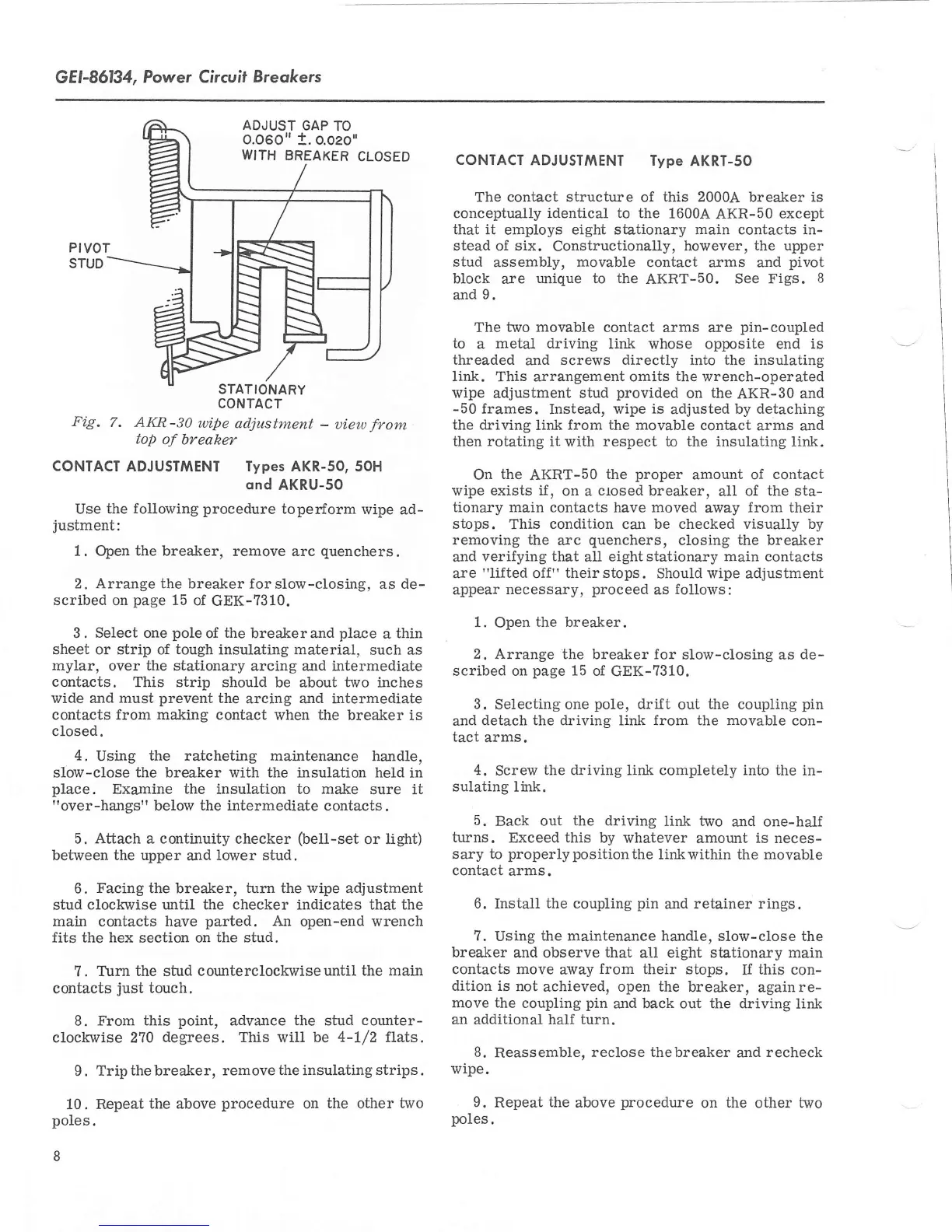
ADJUST
GAP TO
0.060"
t.
o.oeo'
WITH
BREAKER
CLOSED
PIVOT
STUD
STATIONARY
CONTACT
Fig.
7. AKR-30
wipe
adjustment
-
uieoo
from
top
of breaker
CONTACT ADJUSTMENT Types AKR-SO, sOH
qnd
AKRU-SO
Use the
follorving procedure
toper{orm
wipe ad-
justment:
1.
Open the breaker,
remove arc
quenchers.
2. Arrange the breaker forslow-closing,
as de-
scribed on
page
15
of
GEK-7310.
3.
Select one
pole
of
the
breakerand
place
a
thin
sheet or
strip of
tough
insulating
material,
such
as
myl.ar,
over
the
stationary arcing and
intermediate
contacts.
This strip
should be about
two
inches
wide and must
prevent
the
arcing and intermediate
contacts from making contact
when
the
breaker is
closed.
4.
Using
the ratcheting maintenance
handle,
slow-close the breaker with the insulation held in
place.
Examine
the
insulation to make
sure it
"over-hangs"
below
the intermediate
contacts
.
5. Atiach
a
continuity
checker
(bell-set
or
light)
between
the upper
and
lower stud.
6.
Facing the
breaker,
turn
the wipe adjustment
stud
clockwise until the checker
indicates
that the
main
contacts
have
parted. An
open-end
wrench
fits the hex section on
the
stud.
?. Turn
the
stud
counterclockwiseuntil
the main
contacts
just
touch.
8.
From this
point,
advance the stud
counter-
clockwise 270
degrees.
This will be
4-1/2 flats.
9.
Trip the breaker,
remove the insulating strips.
10.
Repeatthe above
procedure
on
the
other
two
poles.
8
CONTACT
ADJUST|YIENT
lype
AKRT-50
The contact structure of this 2000A
breaker
is
conceptually identical to the
1600A
AKR-50
except
that it
employs
eight stationary main contacts in-
stead of six.
Constructionally,
however,
the upper
stud
assembly,
movable
contact arms and
pivot
block
are
unique to the
AKRT-50.
See Figs.
8
and
9.
The
two movable
contact arms are
pin-coupled
to
a
metal driving
link whose
opposite
end is
threaded
and
screws
directly
into
the insulating
link. This arrangement omits
the
wrench-operated
wipe
adjustment
stud
provided
on
the
AKR-30
and
-50
frames.
Instead,
wipe is
adjusted
by detaching
the
driving link
from the
movable contact
arms and
then rotating it
with
respect to the insulating
link.
On
the
AKRT-50
the
proper
amount of
contact
wipe exists if
,
on a
closed
breaker,
aII
of the sta-
tionary main contacts have moved
away
from their
stops.
This
condition can be checked visually by
removing the
arc
quenchers,
closing the breaker
and
verifying
that
all
eightstationary
main
contacts
are
"lifted
off"
their
stops.
Should wipe adjustment
appear
necessary,
proceed
as
follows:
1.
Open
the breaker.
2.
Arrange the breaker for
slow-closing as
de-
scribed on
page
15 of
GEK-7310.
3.
Selecting one
pole,
dri-ft
out
the
coupling
pin
and
detach the drivinE
link
from the movable con-
tact
arms.
4.
Screw
the driving link completely into the
in-
sulating
link.
5.
Back out
the driving
tink two
and one-half
turns.
Exceed this by whatever
amount
is neces-
sary
to
properlypositionthe
linkwithin the movable
contact
arms.
6. Install the coupling
pin
and retainer
rings.
?.
Using
the maintenance handle,
slow-close the
breaker
and observe
that
all
eight stationary main
contacts move
away
from
their stops.
If
this
con-
dition is
not
achieved, open the
breaker,
againre-
move the
coupling
pin
and back out the driving
link
an additional half
turn.
8.
Reassemble,
reclose thebreaker
and
recheck
wipe.
9.
Repeat
the
above
procedure
on
the
other two
poles.
 Loading...