Equipment Overview
2001989-351A ApexPro™ 2-13
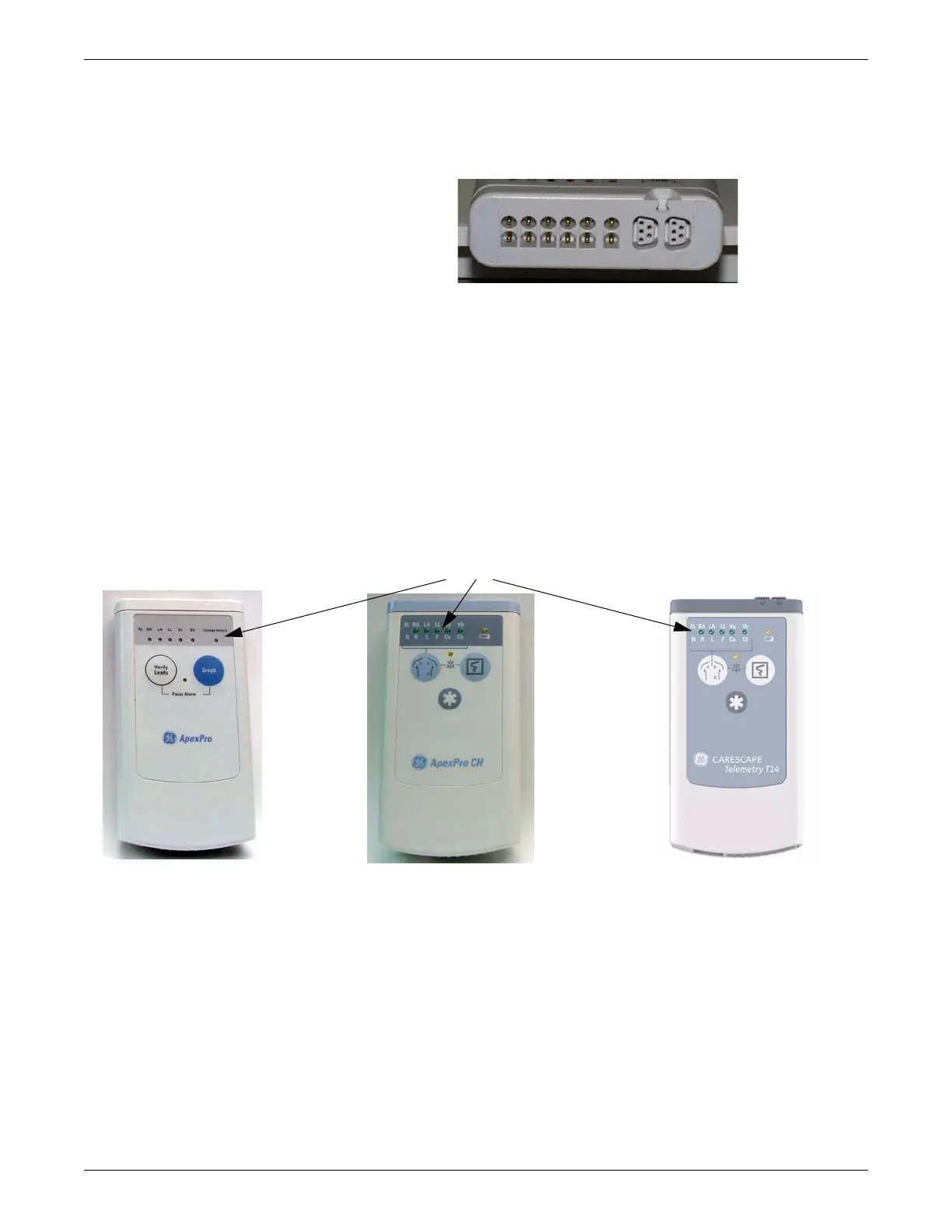
RA shield functions as the RF antenna for the ApexPro and ApexPro CH transmitter;
the T14 transmitter has an internal antenna.
317A
Interface connector ports
When enabled, interface connector ports provide an asynchronous communication
connection to other devices (NBP, SpO2, etc.) for extra monitoring or for service
connection to a programming box.
Switches/LEDs
When power is applied to the transmitter, all of the LEDs should flash rapidly
indicating code is being loaded. The code is done loading and executed when just the
top row LEDs flash twice.
605A, 205B
While in normal application mode, pressing and releasing the Verify Leads button
causes the LEDs to light up for 1 minute if their corresponding lead is good. Pressing
and releasing the Graph button causes either a save or a manual graph at the CIC Pro
center.
Pressing both the Verify Leads and the Graph buttons together causes an alarm
pause condition for the programmed amount of time (typically 5 minutes) or until the
alarm pause action is initiated again. When the transmitter is in alarm pause, the
corresponding LED flashes once every second at a 1/8th duty cycle.
Upon any activation (Verify Leads, Graph, or Alarm Pause) the top row of LEDs
flash twice. All these functions are disabled in service mode.
 Loading...


