© 2003 GE Interlogix B.V. xxxxxxx
All Rights Reserved 12/2004
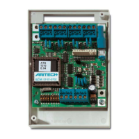
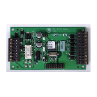
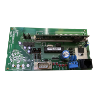
4/8-Zone DGP
MOUNTING THE UNIT
The PCB can be mounted in any existing ATS series enclosure
that supports the BB format.Connections
J1
COMMS 12 VDC power supply. It is recommended that where
the distance between an ATS1220 and the nearest
device is more than 100 meters, a separate power
supply be used.
COMMS Positive and negative data connection of the system
databus. Units can be up to 1.5 km from the 4-lift
DGP or the ATS control panel, depending on the
cable used. See the ATS control panel installation
guide for details.
TAMP Connect the enclosure tamper switch across
these terminals (Tamper switch requires
normally open contacts.)
J2/J3
Each zones requires a 4k7 end-of-line resistor (1 or 2
depending on single or dual zone monitoring programmed
in ATS control panel).
J4
+12 VDC supply and open collector or data output for output
connection to ATS 1810, ATS 1811 and ATS 1820 output cards
via 10-way cable supplied with the output card. Up to sixteen
outputs are available with 8-way or 16-way open collector cards
(4-way and 8/16-way output cards cannot be used together
on the same DGP)
LINKS
Earth connection. Earth wires from all pieces of
equipment must be earthed at one system earth.
For further detail see the ATS control panel
installation guide.
“INT./EXT. TAMP” JUMPER SETTINGS }
INT Tamper switch SW4 + switch on backside SW5 of
the PCB are used (eg. in combination with ATS1644,
plastic housing).
EXT Tamper connections on connector J1 (T, C) are
used for an external tamper switch (eg. In
combination with ATS1643, metal housing).
DGP DIPSWITCH SETTINGS
ADDR { Dip switches 1 to 4 are used to identify the DGP
number.
ABCT |
T Set switch T on if this device is the last device on the
system databus. For more details see the ATS
control panel installation guide.
A,C Not in use
B ON - ATS1811 8-way relay card or ATS1820 16-way
open collector card connected to J4.OFF - no
ATS1811 or ATS1820 connected to J4. Use this
setting also if an ATS1810 is connected to J4.
ZONE NUMBERING
A 4/8-zones DGP can have four or eight zones connected to it.
There are 16 zones allocated to every DGP address. Only zones 1
to 4 or 1 to 8 can be used when an ATS1210/1211/1220 is
allocated a DGP number. Zones not available (5 - 16) or (8-16)
should be programmed as type 0 (zone disabled) in the Zone
database.
Control panel 1 – 16 DGP8 129 - 144
DGP1 17 - 32 DGP9 145 - 160
DGP2 33 - 48 DGP10 161 - 176
DGP3 49 - 64 DGP11 177 - 192
DGP4 65 - 80 DGP12 193 - 208
DGP5 81 - 96 DGP13 209 - 224
DGP6 97 - 112 DGP14 225 - 240
DGP7 113 - 128 DGP15 241 - 256
Note 1:The ATS1210/1211/1220 cannot be expanded to provide
additional zones.
TS1210/1211/1220
4/8-Zone DGP
+
-
D+
D-
T
C