– 31 –
(Continued next page)
6. Disconnect the ON/OFF switch wire harness
from the switch or the main board connectors
CN107 and
CN109.
Electronics Cover
ON/OFF Switch
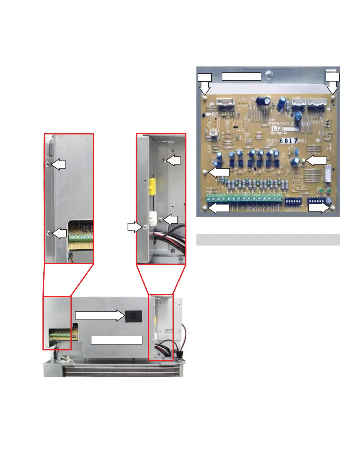
7. Disconnect wire harnesses located at CN1, CN3,
CN4, and CN6.
8. Compress the 6 compression pins, then pull
main board from the bracket.
Pin
Pin
Pin
Metal Bracket
Drive Board
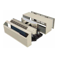
The main power connector receptacle receives line
voltage from the cord or direct connection kit and
supplies power to the drive board.
The drive board contains all of the circuits and logic
which control the relays for the heater, compressor,
and fan motors. The only components on the board
that are replaceable are the fuses. None of the
relays and other electronic components mounted
on the circuit board are replaceable in the fi eld. If a
component on the board (except for fuses FU101,
FU102, and FU103) malfunctions, the board must be
replaced as a complete assembly.
Check for 24 VAC on the drive board at CN101
between pin 1 and pin 2.
If the 4-amp fuse (FU102), has failed, check the fan
motors for a problem.
The drive board is located behind the electronics
cover. The front panel must be removed to remove
the electronics cover and access the drive board.
The drive board is attached to the front bulkhead
with 8 compression pins.
Note:
• In the following step, the electronics cover is
attached to the front bulkhead with 5 Phillips-
head screws and 2 tabs. One tab is located on
the top and the other tab is located on the left
side of the cover. Both tabs are inserted into
slots in the front bulkhead.
• The ON/OFF switch is attached to the electronics
cover and is connected to the main board.
5. Remove the 5 Phillips-head screws, then slide
the cover to the right.
Pin
Pin
Pin