– 32 –
To remove the drive board:
1. Remove the electronics cover. (See Main Board.)
Note: It may be helpful to observe the appearance
of bundled wiring behind the electronics cover. In
the following steps, it will become necessary to
cut off a plastic wire tie that attaches wiring to the
divider plate. Replace the plastic wire tie before
installing the electronics cover.
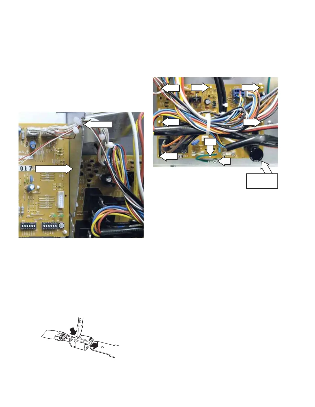
2. Carefully cut off the plastic wire tie that attaches
main board wiring to the divider plate.
3. Disconnect wire harnesses from CN101, CN102,
CN103, CN107, CN108, and CN109.
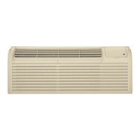
Note: Most of the electrical components in the unit
share wire terminals that use a small clip that holds
the wire fi rmly to an electrical terminal. To remove
the wire from the terminal, depress the clip using
a small blade screwdriver, and pull the wire off the
terminal as shown.
Wire Tie
Divider Plate
ELECTRICAL TERMINAL
RELEASE/LOCKING TAB
4. Mark and disconnect the wiring from relays
RY101, RY102, RY103, and RY104.
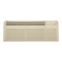
5. Remove the Phillips-head screw and drive board
ground wire from the front bulkhead.
6. Release the 8 compression pins, then pull the
drive board from the front bulkhead.
Pin
Pin
Pin
Pin
Pin
Pin
Pin
Pin located at
board corner