– 33 –
TEST CAPACITOR
RATED
VOLTAGE
COMPRESSOR
TERMINALS
START
RUN
S
C
R
COMMON
TEST KIT
GROUND GROUND
TO UNIT
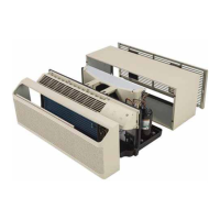
Capacitor
The compressor run capacitor is attached to the
front bulkhead with a strap and a Phillips-head
screw. The control cover must be removed to access
the capacitor. (See Main Board.)
The top of the strap is inserted into a slot in the front
bulkhead.
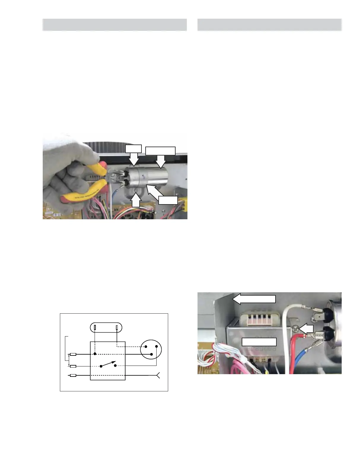
WARNING: The capacitor must be discharged.
Discharge the capacitor between the 2 connectors
using a pair of long-nose pliers with an insulated-
handle.
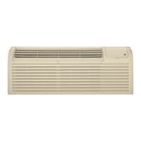
Run Capacitor Check
1. Replace unit run capacitor with a known good
test capacitor, which may be 10 fd higher than
specifi ed, and attempt to start the compressor.
2. If the compressor starts, install a new run
capacitor that has a rating specifi ed for the unit.
Strap
Capacitor
Slot
Transformer
The transformer supplies 24 VAC to the drive board
at location CN101. Check for line voltage on the
power supply board at CN101 between pins 5 and 7.
With power disconnected, check for winding
resistances at the following locations:
• CN101 pin 5 to pin 7 is approximately 100
(230/208 VAC primary).
• CN101 pin 1 to pin 2 is approximately 1.5
(24 VAC secondary).
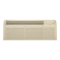
The transformer is attached to the front bulkhead
with a Phillips-head screw. The control cover must
be removed to access the transformer. (See
Main
Board.)
The left side of the transformer is inserted into a slot
located behind the divider plate.
To remove the transformer:
1. Remove the electronics cover. (See Main Board.)
2. Disconnect the wire harness from the drive
board location CN101.
3. Remove the Phillips-head screw from the right
side of the transformer.
4. Slide the transformer to the right, then
maneuver it out from the front bulkhead.
Divider Plate
Transformer