– 34 –
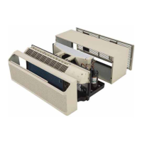
Resistance Heater Assembly
The heater assembly consists of three 265 VAC or
230/208 VAC resistance heating coils fastened to-
gether in a single assembly. The heaters are located
behind the indoor coil and are protected against
overheating by 2 thermal protectors. An L185-30
thermal protector is used as a temperature regula-
tor. A one-shot L248 thermal protector is used as a
backup in case the temperature regulating thermal
protector fails (stuck closed).
Heat Pump models will utilize electric resistance
heat upon initial heat mode startup or when a pow-
er outage has occurred with the unit in heat mode.
The electric heaters will be energized until the room
temperature reaches the thermostat setting. Once
the thermostat temperature setting is attained, the
unit will cycle off and automatically switch over to
heat pump operation. The heat pump will provide all
heating requirements for subsequent cycles unless
one of the following conditions occurs:
• The dip switch has been placed in the I2R (ALL
ELECTRIC HEAT) position. When the dip switch is
placed in the up position, heat pump operation
will be locked out. Only electric resistance heat
will be available.
• A temperature differential of approximately
2°F (temperature differential varies by
thermostat manufacturer) is detected between
the thermostat set point and the room air
temperature. If a differential of approximately
2°F is detected, due to thermostat adjustment or
falling room air temperature, the electric heaters
will be energized (heat pump off) until the
thermostat is satisfi ed. Once the thermostat has
been satisfi ed, the unit will automatically revert
to heat pump operation for subsequent cycles.
• If the outdoor temperature falls below 25°F, the
unit will automatically switch from heat pump
operation to resistance heat operation. A 7°F
hysteresis loop will be in effect; therefore, the
unit will operate in resistance heat mode until
an outdoor temperature of 32°F or higher is
detected.
Electric resistance heat and heat pump operation
will never occur at the same time.
Models without heat pump feature will meet heating
requirements by using electric resistance heating
coils.
To Test Heaters and Thermal Protectors:
Thermal protectors are wired in series with each
other and with each heating coil. The following test
verifi es that both protectors have continuity and the
heater coil tested has the proper resistance value.
Test for the following resistance values between
the black wire on RY103 to each of the 3 wires in
the heater assembly harness. An open reading will
require accessing the heater assembly for further
diagnosis.
Heater Resistance Values
RY103 black to heater
connector pin 1
230/208 VAC: 50 Ω
265 VAC: 66Ω
Upper Coil
RY103 black to heater
connector pin 2
230/208 VAC: 32 Ω
265VAC: 42 Ω
Lower Coil
RY103 black to heater
connector pin 3
230/208 VAC: 20 Ω
265VAC: 26 Ω
Middle Coil
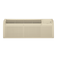
To remove the resistance heaters:
1. Remove the front panel and slide the chassis
forward approximately 5 inches. (See
Slide-Out
Chassis.)
2. Remove the 6 Phillips-head screws and the
corner sheet metal panel fastened to the left
side of the indoor coil.
Left Side Panel
(Continued next page)