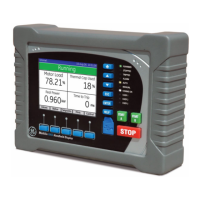
1900/27 Vibration Monitor Operation and Maintenance Manual
34
7. With the sinewave generator powered off, measure the DC voltage
across the “LOOP +” and “TEST” connections on the 4 to 20 mA
terminal block. The voltage should be about 0.40 Vdc. If it is not,
adjust the zero adjust potentiometer (R16) until the voltage is 0.40
Vdc.
8. Turn the sinewave generator on and adjust the output of the
generator for a 1.30 V
rms
at 614 Hz. The LCD display should read
about 46.7 mm/s (1.840 ips).
9. Measure the RMS voltage on the output on the Buffered Transducer
output connector. The multimeter should read 0.65 V
rms
. If it does
not, adjust the output of the sinewave generator either up or down
until the buffered transducer output is 0.65 V
rms
.
10. Measure the DC voltage between the LOOP+ and TEST connectors
of the 4 to 20 mA terminal block. The reading on the multimeter
should be 1.87 V
dc
. If it is not, adjust the gain adjust potentiometer
up or down until the voltmeter reads 1.87 V
dc
.
11. If desired, verify the accuracy of the loop by adjusting the output of
the sinewave generator to 0.707 V
rms
and measuring the voltage
between LOOP+ and TEST. The reading should be between 1.18 V
dc
and 1.22 V
dc
. If it is not, repeat Steps 7 through 10 of this procedure.
12. Turn off the sinewave generator.
13. Unplug the power cable from both the monitor and 4 to 20 mA
power sources.
14. Disconnect the power cable from the power supply terminal strip.
15. Disconnect the resistors, jumper wires and sinewave generator
from the transducer terminal strip.
16. Snap the case cover back into place over the printed circuit boards.
 Loading...

