Dishwasher Installation
8
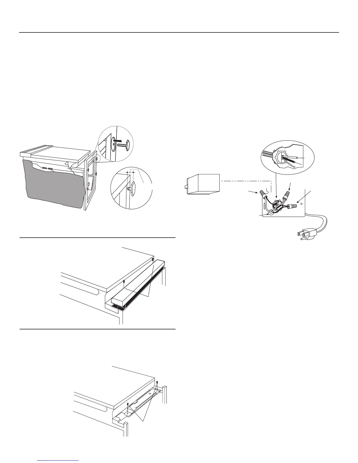
Figure M
STEP 6 – REMOVE TOEKICK BRACE
Skip this step if your model does not have a sound upgrade
kit. If your model does have a sound upgrade kit, this brace
must be removed.
• Remove the 2 toekick brace
screws and
toekick brace.
Discard brace
and set
screws aside
for use in
Step 23.
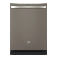
STEP 4 – REMOVE WOOD BASE,
INSTALL LEVELING LEGS
IMPORTANT – Do not kick off wood base! Damage
will occur.
• Move the dishwasher close to the installation location and lay
it on its back.
• Remove the four leveling legs on the underside of the wood
base with an adjustable wrench or 15/16" socket.
• Discard base.
• Screw leveling legs back into the dishwasher frame
approximately 1/8" from frame as shown.
Approx.
1/8"
Figure L
Remove 2
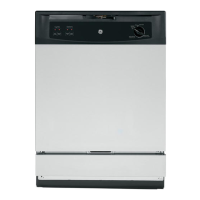
STEP 5 – REMOVE TOEKICK
• Remove the 2 toekick screws
and toekick.
Set aside
for use in
Step 24.
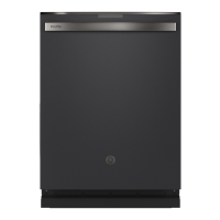
White
Ground
Black
STEP 7 – INSTALL POWER CORD
Skip this step if dishwasher will be permanently connected
to the house electrical system.
In this step you will need the junction box cover and the
#10 x 1/2" hex-head screw from the screw kit set aside in
Step 1.
The power cord and connections must comply with the
National Electrical Code, Section 422 and/or local codes and
ordinances. Maximum power cord length is 6 feet. Power Cord
Kit WX09X70910, available for purchase from an authorized
GE Appliance Dealer, meets these requirements.
• Install strain relief in junction box bracket.
• Insert power cord through strain relief and tighten.
• Make sure black, white and green dishwasher wires are
threaded through small hole in junction box bracket.
• Connect like-colored dishwasher and power cord wires. If
power cord wires are not color-coded, connect the ribbed
power cord wire to the white dishwasher wire, the smooth
power cord wire to the black dishwasher wire and the ground
to the green dishwasher wire. Use UL-listed wire nuts of
appropriate size.
• Install junction box cover set aside in Step 1, using #10 hex-
head screw. Be sure wires are not pinched under the cover.
Figure K
Figure N
Remove 2
Toekick Screws

 Loading...