EasyManua.ls Logo

GE Carestation 650c User Manual

GE Carestation 650c
6 pages
To Next Page IconTo Next Page
Page #1 background imageLoading...
Page #1 background image
M1807013 Rev. F 01 15 Page 1 of 6
M1807013-DWG
Installation Instructions, For Field Use
For future reference add to your Technical Reference Manual
Installation and Service Instructions for Carestation 650c Pendant anesthesia machine
Read through these entire instructions before beginning the installation.
This document contains confidential information or proprietary information of General Electric Company or its af-
filiates. Neither the document nor the information therein is to be reproduced, distributed, used, or disclosed, either
in whole or in part, except as specifically authorized in writing by a General Electric Company and must be returned
upon request.
Datex-Ohmeda, Inc.
3030 Ohmeda Drive
PO Box 7550
Madison, WI 53707-7550, USA
WARNING This pendant mount anesthesia machine must be installed by GE Healthcare
Authorized service personnel having experience with anesthesia machine
equipment.
WARNING This device, when removed from its ceiling mount, does not meet the
stability requirements of IEC 80601-2-13 and IEC 60601-1 respectively. Special
caution has to be taken.
Carestation 650c Pendant anesthesia machines (factory-configured) are designed for attachment to Draeger or
TRUMPF (Kreuzer) or Maquet pendant lift interfaces.
These instructions are for mounting a Carestation 650c Pendant anesthesia machine onto a pendant lift.
WARNING Mass limit of the pendant anesthesia system is 180 kg (396 Ibs).
Tools needed
Standard hand tools
Measuring tape
Carestation 600 Series Technical Reference Manual
( PN: 2076163-001)
Installation procedure
1. Verify that the maximum loading allowance of the pendant lift is
sufficient to carry total weight of Carestation 650c anesthesia machine.
Note: Carestation 650c weight and center of gravity location are shown in
APPENDIX 1.
WARNING Do not overload the pendant lift. Make sure the
maximum loading allowance of the pendant lift
is verified and the result is recorded.
2. Lower the pendant lift to the bottom position. Make sure that the
minimum distance from the top of the lift pins to the ground (A) is less than 550 mm (21.65 inches).
Note: If the pendant lift cannot be lowered to above required height, contact the pendant lift supplier to replace the
beam (B).
WARNING Do not proceed with the installation if the pendant lift does not meet above
requirement.
A
B
Top of lift pins
Ground
Question and Answer IconNeed help?

Do you have a question about the GE Carestation 650c and is the answer not in the manual?

GE Carestation 650c Specifications

General IconGeneral
ManufacturerGE Healthcare
ModelCarestation 650c
Power Supply100-240V AC, 50/60 Hz
Oxygen Concentration21-100%
CategoryMedical Equipment
Display15-inch color touchscreen
Battery BackupApproximately 90 minutes (depending on configuration and usage)
ConnectivityEthernet, USB
Ventilation ModesVolume Control, Pressure Control, SIMV
Tidal Volume Range20-1500 mL
Pressure Range5-60 cmH2O
PEEP0-20 cmH2O
Integrated MonitoringYes, with respiratory and gas monitoring
Oxygen FlushYes
VaporizersSupports up to 3 vaporizers (optional)

Summary

Tools Needed for Installation

Installation Procedure Steps

Verify Pendant Lift Load Capacity

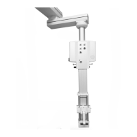
Ensure the pendant lift can support the anesthesia machine's total weight, recording the verification.

Check Pendant Lift Lowered Height

Verify minimum distance from lift pins to ground is less than 550mm (21.65 inches).

Unpack and Prepare Machine

Remove packaging and any extra loads from the anesthesia machine's top shelf and tabletop.

Adjust Tilt Blocks and Screw

Loosen tilt blocks, slide them, and turn the tilt adjustment screw counterclockwise.

Mount Machine to Pendant Lift

Align lift pins with machine mount holes and raise lift until fully mated.

Secure Tilt Blocks and Finalize

Position tilt blocks against the bracket, tighten screws to torque, and reinstall parts.

Connect Power and Gas Supplies

Connect the power cable and gas supplies to the anesthesia machine.

Perform Checkout Procedure

Execute the anesthesia machine Checkout Procedure as detailed in the Technical Reference Manual.

Service Instructions

Prepare for Servicing

Lower the pendant lift so the machine rests on wheels and lift pins retract from mounting holes.

Remove Machine and Service

Move the anesthesia machine away from the pendant lift and perform service activities.

Check Screw Tightness

Verify tightness of sixteen screws during maintenance, checking alignment of adjacent areas.

Remount After Service

Remount the anesthesia machine to the pendant system following the installation instructions.

Appendix 1: Dimensional Data

Related product manuals