CL 5 Issue 01, 04/05 3-3
Connecting a Probe and Loading a Setup File
Setting Up the CL 5
3.1 Connecting a Probe and
Loading a Setup File
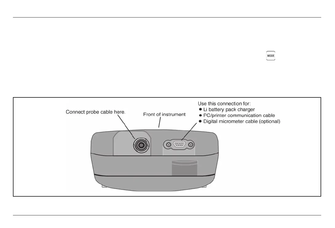
Prior to measuring thickness, you must connect a
probe to the instrument and select a setup file thats
compatible with the probe (Figure 3-1). The CL 5
supports delay line and contact probe types (see
Chapter 7 for specifications).
Once a probe is connected, press to activate the
Probe Setup display. The Probe Setup display, which is
shown in Figure 3-2, allows the user to select a
standard or Custom Setup file (see Section 3.5 to
create or erase Custom Setup files).
FIGURE 3-1Connecting a Probe Cable
CL 5 Issue 01, 04/05 3-3
Connecting a Probe and Loading a Setup File
Setting Up the CL 5
3.1 Connecting a Probe and
Loading a Setup File
Prior to measuring thickness, you must connect a
probe to the instrument and select a setup file thats
compatible with the probe (Figure 3-1). The CL 5
supports delay line and contact probe types (see
Chapter 7 for specifications).
Once a probe is connected, press to activate the
Probe Setup display. The Probe Setup display, which is
shown in Figure 3-2, allows the user to select a
standard or Custom Setup file (see Section 3.5 to
create or erase Custom Setup files).
FIGURE 3-1Connecting a Probe Cable