5-18 170 Series Monitor Revision C
2000947-004
Theory of Operation: Main Board Theory of Operation
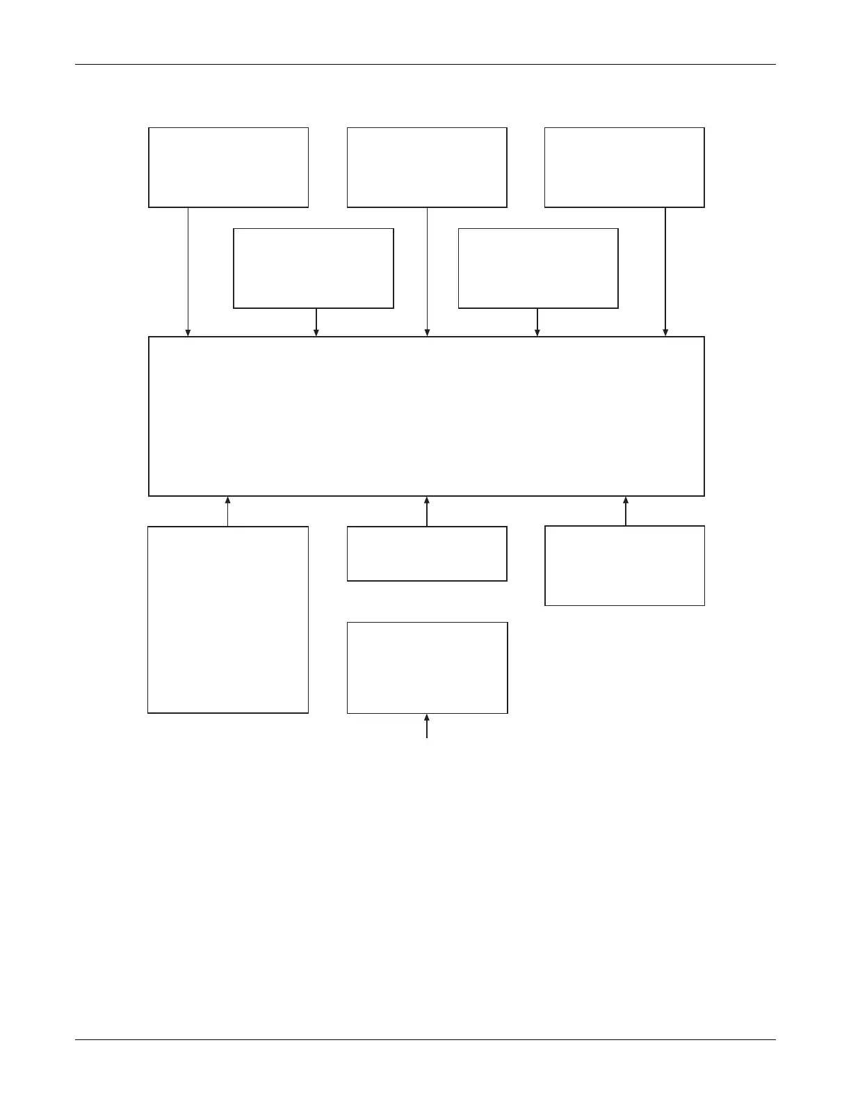
Figure 5-10. Main Board Block Diagram
Audio Module
Audio amplifier
Ultrasound volume controls
ECG/alarm-tone volume
control
Status/Switch Input Module
Front panel switch input
buffers
Rear panel, recorder, and
front-end status buffers
Communications Module
Quad async UART
RS-232 transceivers
Display Interface
Data buffers
ESD protection
Recorder Interface
Motor control latches
Head control latches
Status input buffers
Printhead serial data link
Processing Block
System processor
System flash memory
System boot flash memory
System RAM
System address decoder
PAL
System battery RAM with
real-time clock
System Power Supply
Pre-regulators
+5 V regulators
±3.3 V regulators
+7.5 V regulators (173/174)
+24 V regulators
+11 V regulators (173/174)
Uterine Activity Module
Pressure differential
amplifier
+4 V reference
A/D converter
Ultrasound Module
Ultrasound transmitter
Control logic PAL
Pin diode switches, pre-
amplifier, and demodulator
Ultrasound envelope filters
Ultrasound envelope
detector
Audio frequency doubler
and filters
Fetal movement bandpass
filters
Telemetry multiplexor
A/D converter
Local voltage regulators
+12 V input
Interface to
FECG/UA Board
(173/174)
 Loading...


