Revision C 170 Series Monitor 5-27
2000947-004
Theory of Operation: Main Board Theory of Operation
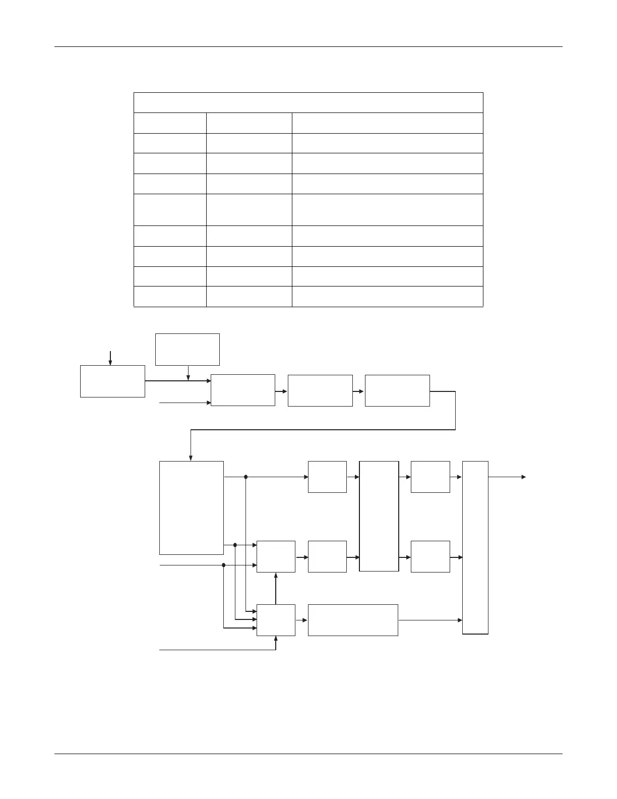
Figure 5-17. Ultrasound Module Block Diagram
Table 5-19. PAL Outputs
Pin Number Signal Name Signal Description
1 TRANS_BURST Operates the Ultrasound Transmitter.
2 DET_BURST1 Activates the Demodulator.
18 575KC Synchronizes the Power Supplies
19 USMODE Signals the Processor that the
US Channel is Active
21 PIN1 Selects Channel 1 Transducer
22 PIN2 Selects Channel 2 Transducer
42 CH2 Selects CH2 Track and Hold Circuit
43 CH1 Selects CH1 Track and Hold Circuit
AGC
Transmitter
Input Pin
Diode Switching
Pre-Amplifier Demodulator
Demultiplexor
Envelope
Detector
CH2
Main
Filter
CH2
Main
Filter
CH1
Telemetry
Switch
Telemetry
Switch
Fetal Movement
Detection Filter
A/D
Telemetry Audio
Control Lines
Envelope
Detector
CH1
CH2
CH1
to Data Bus
US Channel 1
US Channel 2
Isolation
Transformer
(174 only)
 Loading...