GE MEDICAL SYSTEMS CT PROSPEED SERIES INSTALLATION
2124011
3-15
REV 15
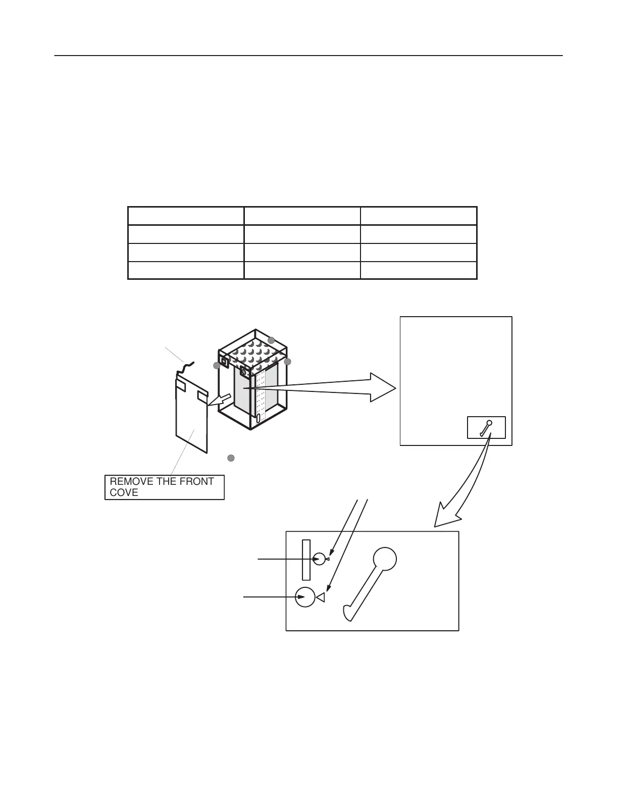
3–1–2 Breaker Activation Level Setting
Activation levels (both magnetic and thermal) should be set on the main circuit breaker (CB20), as follows:
Refer to Illustration 3–11.
1. Remove the front cover while removing the ground cable.
2. Turn the dials so that a setting value (written in the table below) is set to the arrow mark.
(Input voltage is measured at step 8. – a. in Section 3–1–1, Setting Coupling Terminal for Input Voltage.)
INPUT VOLTAGE MAGNETIC SETTING THERMAL SETTING
200 V / 208 V 1000 80
380 V / 400 V / 415 V 800 63
440 V / 460 V / 480 V 600 63
REMOVE THE FRONT
COVER
: FRAME GROUND
POINT
GROUND
CABLE
SET DIAL (THERMAL)
SET DIAL (MAGNETIC)
ARROW
MARKS
CB20
CB20
FRONT SIDE
BREAKER SET DIALS
ILLUSTRA
TION 3–1
1
 Loading...


