GE MEDICAL SYSTEMS CT PROSPEED SERIES INSTALLATION
2124011
3-16
REV 15
3–1–2 Breaker Activation Level Setting (continued)
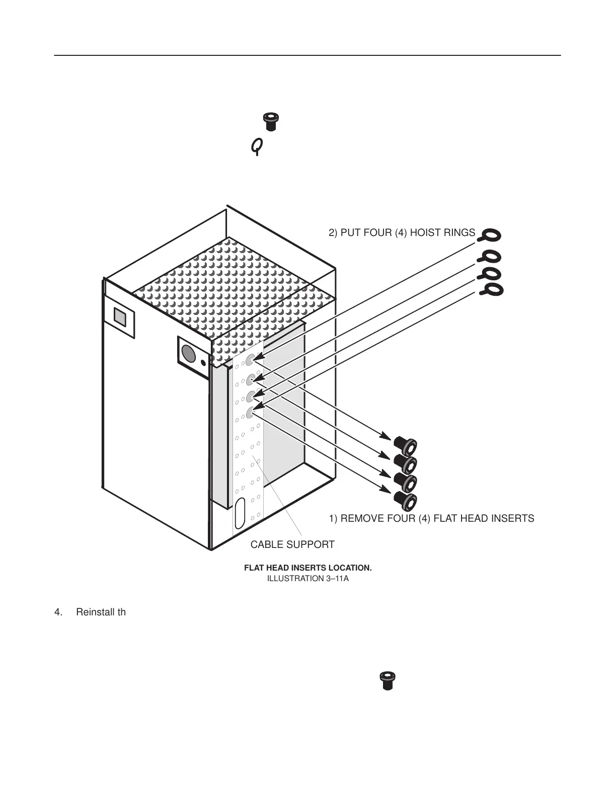
3. Remove four (4) FLAT HEAD INSERTS
from the cable support on the PDU right side.
Afterwards, put four (4) HOIST RINGS
into the cable support.
See Illustration 3–11A.
ÅÅÅÅÅÅÅÅÅÅÅÅÅÅÅ
ÅÅÅÅÅÅÅÅÅÅÅÅÅÅÅ
ÅÅÅÅÅÅÅÅÅÅÅÅÅÅÅ
ÅÅÅÅÅÅÅÅÅÅÅÅÅÅÅ
ÅÅÅÅÅÅÅÅÅÅÅÅÅÅÅ
ÅÅÅÅÅÅÅÅÅÅÅÅÅÅÅ
ÅÅÅÅÅÅÅÅÅÅÅÅÅÅÅ
ÅÅÅÅÅÅÅÅÅÅÅÅÅÅÅ
ÅÅÅÅÅÅÅÅÅÅÅÅÅÅÅ
1) REMOVE FOUR (4) FLAT HEAD INSERTS
2) PUT FOUR (4) HOIST RINGS
CABLE SUPPORT
FLAT HEAD INSERTS LOCATION.
ILLUSTRA
TION 3–1
1A
4. Reinstall the rear and right side covers. See step 7. to step 6.
However, when the rear cover is reinstalled, do not forget to re–connect the fan connector.
5. Reinstall the front cover while connecting the ground cable.
6. Reinstall the top cover using these four (4) FLAT HEAD INSERTS .
7. Verify that the rear side two fans are properly spinning when the PDU is powered up.
 Loading...


