GE MEDICAL SYSTEMS CT PROSPEED SERIES INSTALLATION
2124011
3-17
REV 15
3–2 OPERATOR CONSOLE (Qj–b TYPE)
Note
This section applies to Qj–b Type OC.
For Zj Type or Zj–a Type OC, See Section 3–3, OPERATOR CONSOLE (Zj/Zj–a TYPE).
3–2–1 Operator Console (OC)
NOTICE
The OC contains a hard disk drive unit and other fragile equipment.
Take care when moving the OC unit.
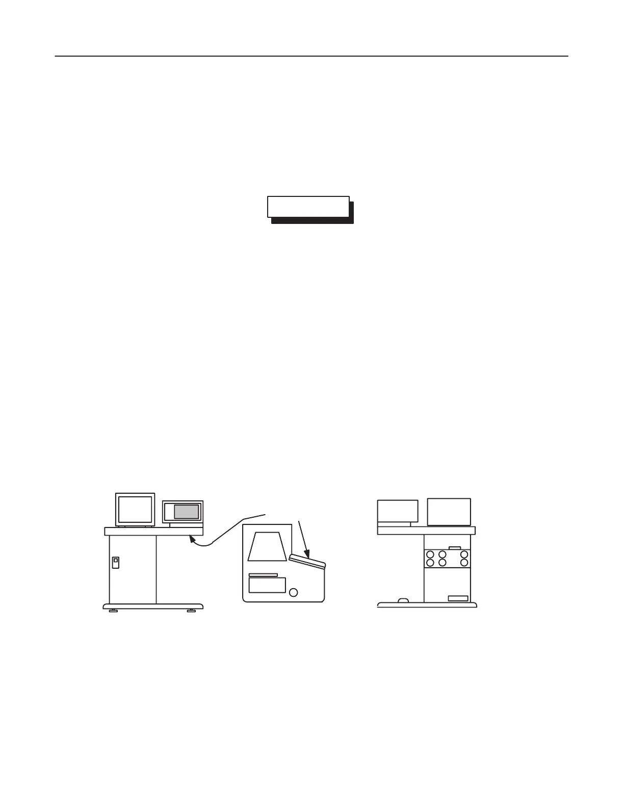
1. Move the OC to the Operator Console room using its casters.
Note
Position the OC so the operator can see the patient on the table from the console.
2. Remove
the LCD touch panel tilt angle adjustment plate under the LCD touch panel and pivot the touch screen
into place; ask the customer what angle is best or adjust the screen to minimize glare.
Refer
to Section 1–6, T
OUCH P
ANEL (LIQUID CR
YST
AL DISPLA
Y), of tab 1 of the Component Replacement
manual (2124012), if necessary.
3. Remove
the two rubber caps and two screws
from the top of the Operator Console and remove the top cover to
allow access for system wiring
Refer to Section 4, SYSTEM POWER, GROUND AND CABLE INTER–CONNECTION.
4. Remove the rear (upper and lower) and front covers to allow access for system wiring.
FRONT VIEW TOP VIEW
LCD TOUCH
PANEL
TILT ANGLE
ADJUST-
MENT
PLATE
OC REAR VIEW
OPERATOR
CONSOLE
ILLUSTRA
TION 3–12
 Loading...


