GE MEDICAL SYSTEMS CT PROSPEED SERIES INSTALLATION
2124011
3-22
REV 15
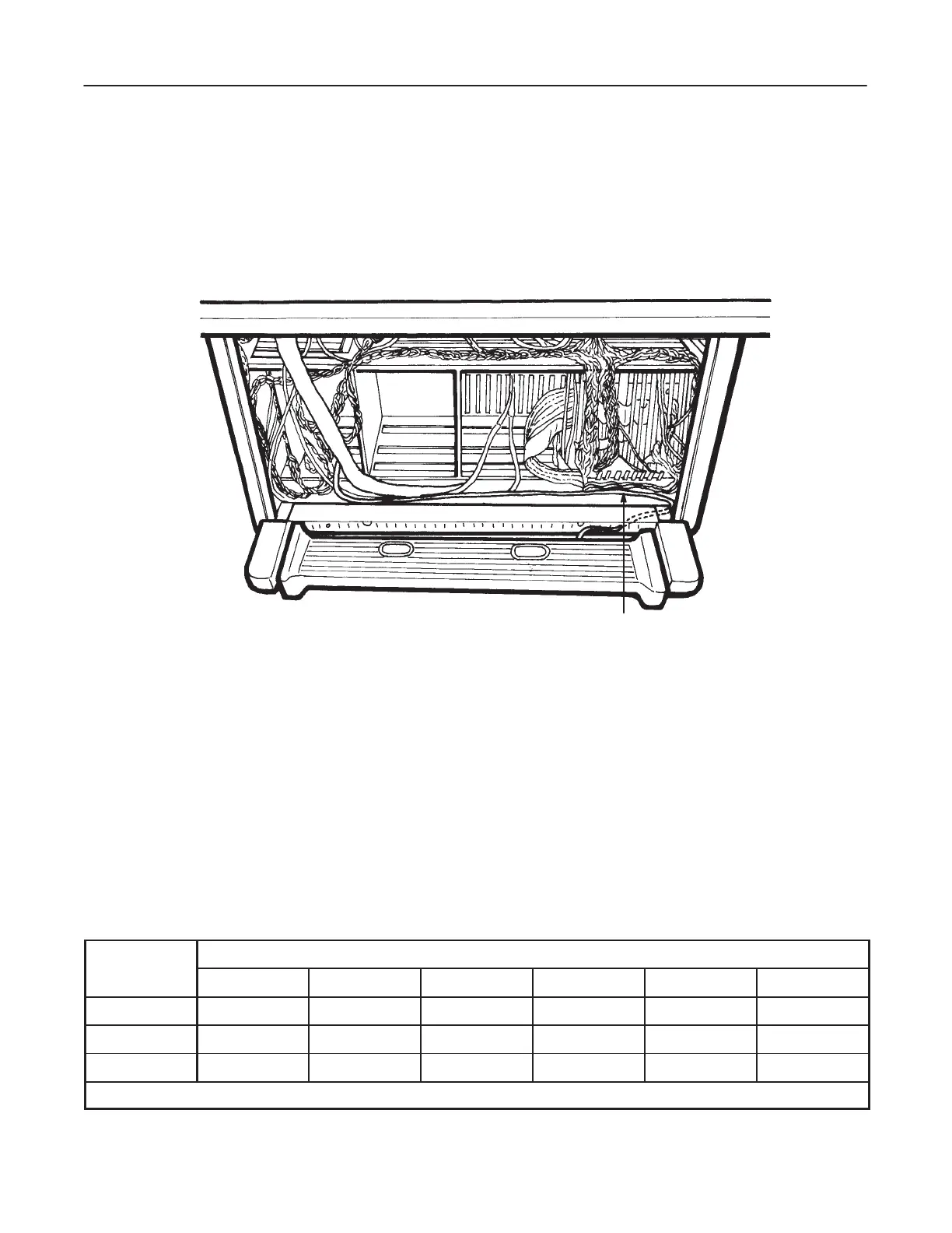
3–3–3 Foot Switch Assy
1. Remove the front cover and note the location of the Foot Switch Assy.
2. Connect
the foot switch cable from the Foot Switch Assy to CN9 on the OC INTF3 board (Slot #44) as shown in
Illustration 3–17.
FOOT SWITCH CABLE
FOOT SWITCH CABLE WIRING
ILLUSTRA
TION 3–17
3–4 OPTION BOARD LOCATIONS
Note
This section applies to Qj Type, Qj–b Type, or Zj–a Type OC.
Option boards such are ETC, MTC, ... should be inserted into the correct slots according to Table 3–1.
TABLE 3–1
OPTION BOARD SLOT #
OC SLOT #
ETC COMX/NEMA MTC ODC2 SCSI ISC
Qj Type 9 – – – 8 7
Qj–b Type 10 – – – 9 8
Zj–a Type 15 14 13 12 11 10
Note SCSI, ISC: standard boards for all the types of OC –: means “not available”
 Loading...


