GE MEDICAL SYSTEMS CT PROSPEED SERIES INSTALLATION
2124011
3-23
REV 15
3–5 MOD INSTALLATION
Note
This section applies to Qj Type or Qj–b Type OC.
Note
SCSI
Board Jumber/Dip swtich setting and OC Back
board Setting should have been performed be
-
fore shipment. (They can be referred to CD–ROM, Functional Check/Adjustment, Board/Device
Jumper/Switch setting, Operator Console, Back Board or Circuit Boards in Nest Chassis.)
3–5–1 Installation
Cable Connection
1. Turn
OFF the OC power
, then remove the OC
front, rear and top covers (including rear inner cover over back
-
plane).
2. Connect MOD Power, signal, and GND cables to the OC.
This
procedure must be performed when connecting system or ground cables. Refer to Section 4–2–3 OC Cable
Connection of this manual.
DC Power Check and Custom Parameter Setting
3. Switch
ON the OC power and MOD Drive Unit power
,
and verify that the R/W indicator is flashing ON and OFF
.
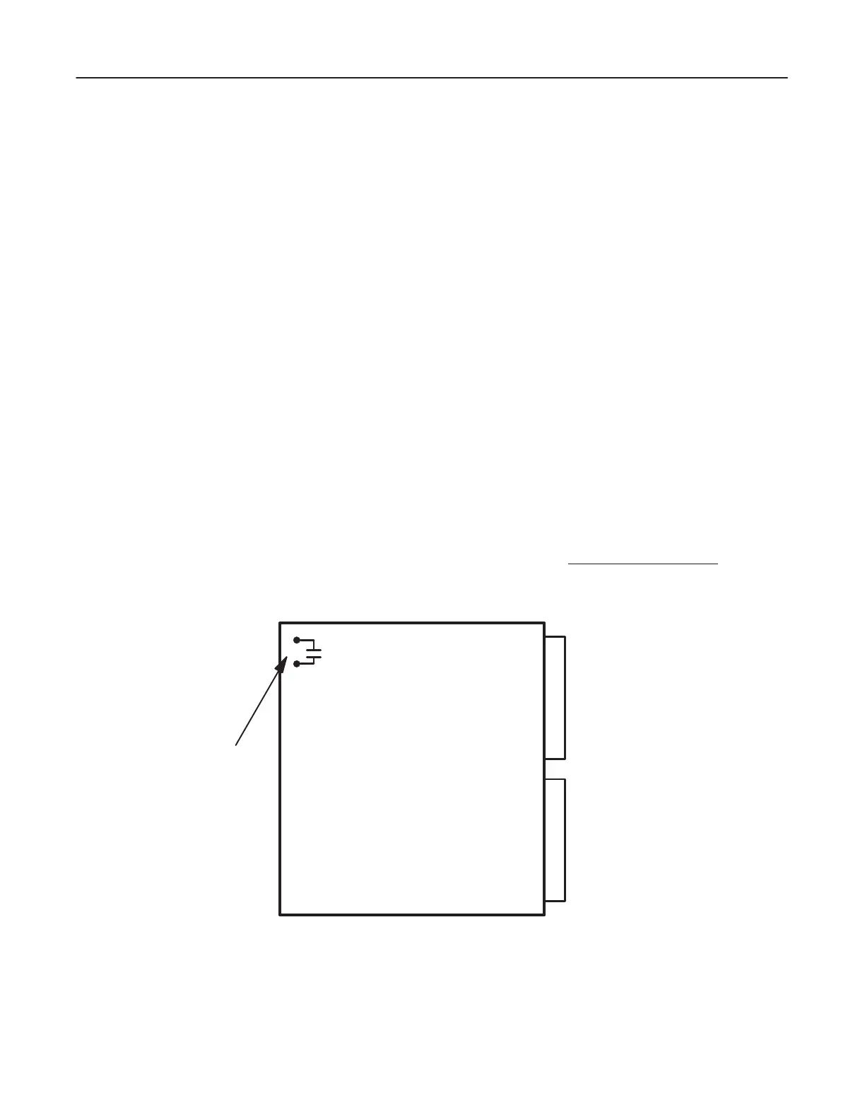
4. Measure
the +5VDC by connecting a DVM to the pins of the T
antalum capacitor terminals on the IPU Assy
(or
IPU2
Assy; slot 2). See
Illustration 3–18. Then adjust the voltage between
+5.0VDC and +5.1VDC
with a trim
-
mer adjuster/tweaker (small slotted screw driver). See Illustration 3–19.
10mF Cap.
Connect the DVM across
the capacitor’s terminals.
IPU
(OR IPU2) T
ANTALUM CAPACIT
OR LOCA
TION
ILLUSTRA
TION 3–18
 Loading...


