GE MEDICAL SYSTEMS CT PROSPEED SERIES INSTALLATION
2124011
3-33
REV 15
3–7–2 OC Modification (continued)
b. OVL2 ASSY (Slot # 12)
Verify that the Resistor modules at location 17A1, 17A2, 19A1 and 19A2 are installed correctly.
17A1 330 W (U1222 RL).
. . .
17A2 330
W
(U1233 RL).
. .
19A1
1 K W (U1310 RL).
. . .
19A2
c. IFB2 ASSY (Slot # 13)
This board has no jumper and no switches to adjustment.
d. FCP2A ASSY (Slot # 15)
Set all the Dip switches (SW 14A1) to OFF.
e. FCP1 ASSY (Slot # 16)
This board has no jumper and no switches to adjustment.
f. FCP3B ASSY (Slot # 17)
Set the Dip switches (SW 14A1) as follows.
FMD
OPTION (DC III : Slot #18)
OFF OFF ON OFF
STANDARD OFF OFF OFF OFF
1234
g. FMD ASSY (Slot # 18)
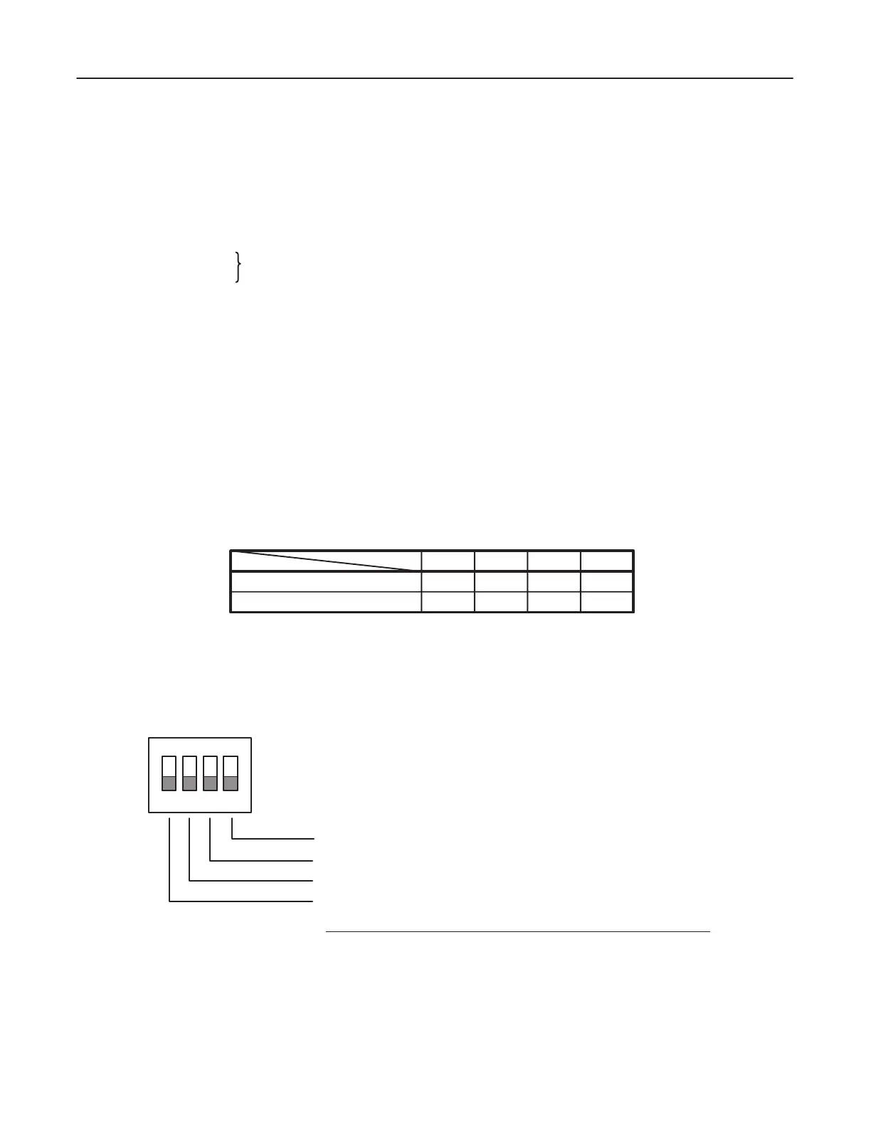
Set all the SW 08A1 Dip Switches to OFF.
D SW08A1 – FMD Address Mapping. Normally set as illustrated below
ON
1234
’1’
’0’
B0 : Not used. Set to ’0’
B1 : Not used. Set to ’0’.
B2–B3 : FMD Address Mapping on SYSTEM BUS
B3(SW1) B2(SW2) Address(Hex)
0 0 1800000 – 2FFFFFF
0 1 3000000 – 47FFFFF
1 0 2000000 – 37FFFFF
1 1 3800000 – 4FFFFFF
 Loading...


