D20/D200 Technical Overview
GE Information PRPI-019-3.00-10
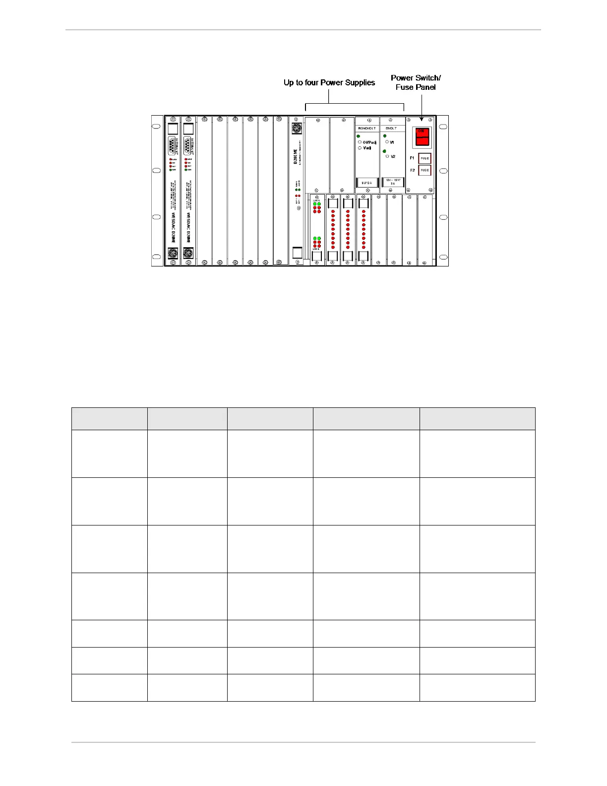
Figure 37 D200 Power Supplies
2.5.1 D20 Power Supply Specifications
The following table gives details of the standard chassis-mounted, auxiliary and redundant power
supplies that are available. Other power supplies are available for specific requirements. Contact
GE Grid Solutions for details.
Table 20 D20/D200 Power Supplies
Type Part Number Input Output Mounting
Chassis-
mounted (D20)
580-2004 20 – 60 VDC +5 V, 7 A
+12 V, 2 A
-12 V, 1 A
24 VDC, 3 A
Chassis
Chassis-
mounted (D20)
580-2005 20 – 60 VDC +5 V, 7 A
+12 V, 2 A
-12 V, 1 A
48 VDC, 1.5 A
Chassis
Chassis-
mounted (D20)
580-2006 100 – 300 VDC
or
85 – 264 VAC
+5 V, 7 A
+12 V, 2 A
-12 V, 1 A
24 VDC, 3 A
Chassis
Chassis-
mounted (D20)
580-2007 100 – 300 VDC
or
+85 – 264 VAC
+5 V, 7 A
+12 V, 2 A
-12 V, 1 A
48 VDC, 1.5 A
Chassis
Chassis-
mounted (D200)
580-0301 48VDC +5 V, 12A Chassis
Chassis-
mounted (D200)
580-0300 48VDC ±12V, 2A ea. Chassis
Chassis-
mounted (D200)
580-0299 115/230VAC +5 V, 12A Chassis


 To Next Page