D20/D200 Technical Overview
GE Information PRPI-019-3.00-10
If detected, the following hardware failures will result in a fail-over from the active to the
standby D20/D200:
• Power failure
• Background diagnostic error
• Bus error
• Watchdog timer reset
When a failure of the active D20/D200 is detected, the standby D20/D200 is switched to an
“active” state, at which point it will initiate data collection and control functionality. The standby
D20/D200 completes a full update of its databases at this time. The originally active D20/D200
is disabled, with no fail-back operation. The standby D20/D200 system remains in the “Active
Polling” state, until manually restored to its original configuration.
A switchover can be manually forced from the RS-232 Switch Panel, or through the
WESMAINT maintenance interface.
2.9.2 D.20 Link Redundancy
In addition to equipment redundancy, the D20/D200 can be equipped to provide D.20 Link
redundancy using D.20 Loop Redundancy or D.20 Link Redundancy. A D20 system with loop
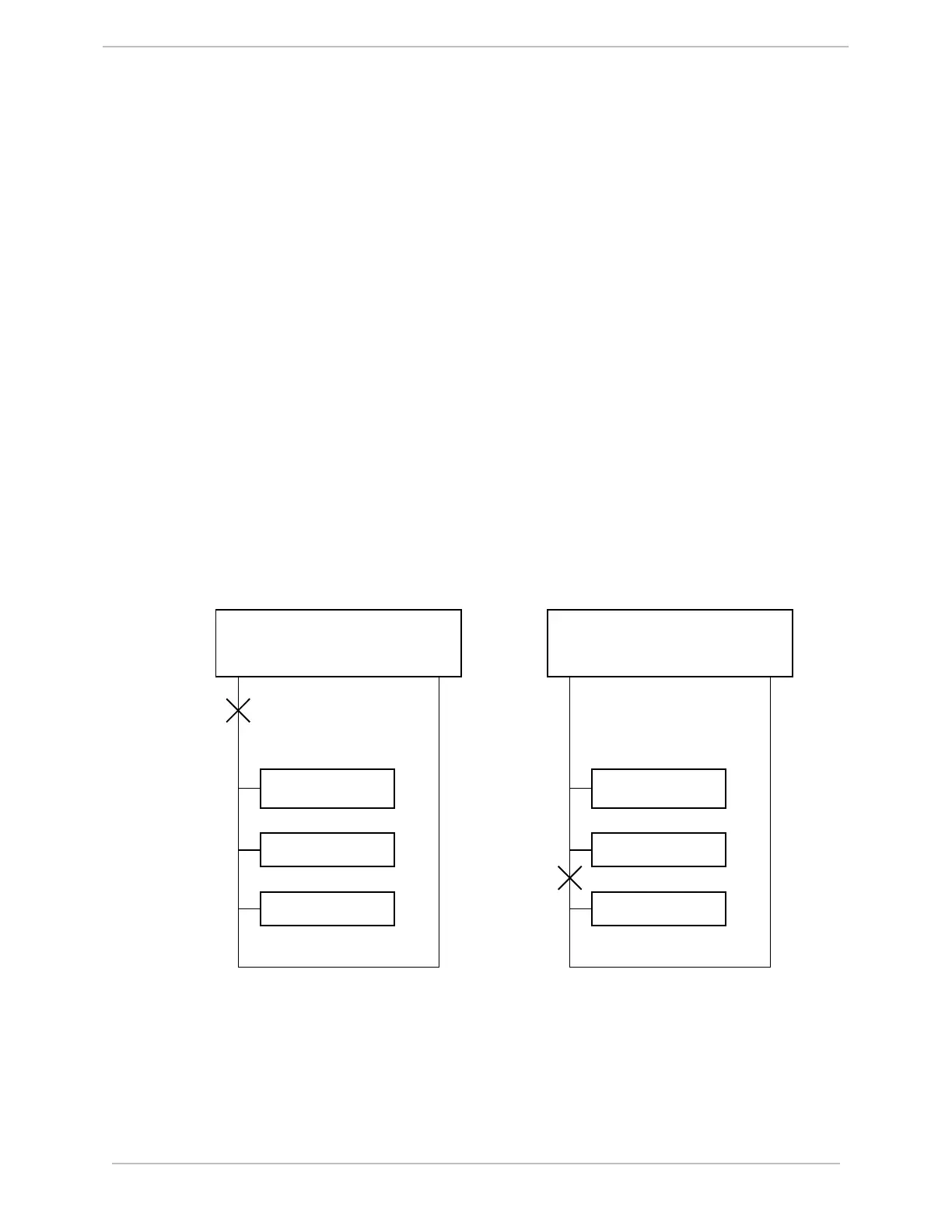
redundancy is illustrated in Figure 45.
D20/D200
I/O Peripheral
I/O Peripheral
I/O Peripheral
D.20 Link A
D.20 Link B
Failure
Scenario 1
D20/D200
I/O Peripheral
I/O Peripheral
I/O Peripheral
D.20 Link A
D.20 Link B
Failure
Scenario 2
Figure 45 Single D20/D200 with Loop Redundancy
With D.20 Loop Redundancy, cabling is daisy-chained from D.20 Port A through all of the I/O
peripherals, then the last I/O peripheral in the chain is connected back to D.20 Port B. Normally,
the D20/D200 will communicate with the I/O peripherals alternately through D.20 Link A and
D.20 Link B. In this way, the D20/D200 is able to regularly confirm the integrity of both


 To Next Page