Installation
1. Turn offthe circuit breaker(s)(30 amp) or remove the dryer's
circuit fuse at the electrical box.
2. Besure the dryer cord is unplugged from the wall receptacle.
3. Remove the power cord cover located at the lower back.
4. Remove and discard ground strap. Keep the green ground screw
for step 7.
5. Install 3/4 in. UL recognized strain relief to power cord entry hole.
Bring power cord through strain reliefi
6. Connect power cord as follows:
A. Connect the 2 hot lines to the outer screws of the terminal
block (marked L1 and L2).
B. Connect the neutral (white) line to the center of the terminal
block (marked N).
7. Attach ground wire of power cord with the green ground screw
(hole above strain relief bracket). Tighten all terminal block
screws (3)completely.
8. Properly secure power cord to strain relief.
9. Reinstall the cover.
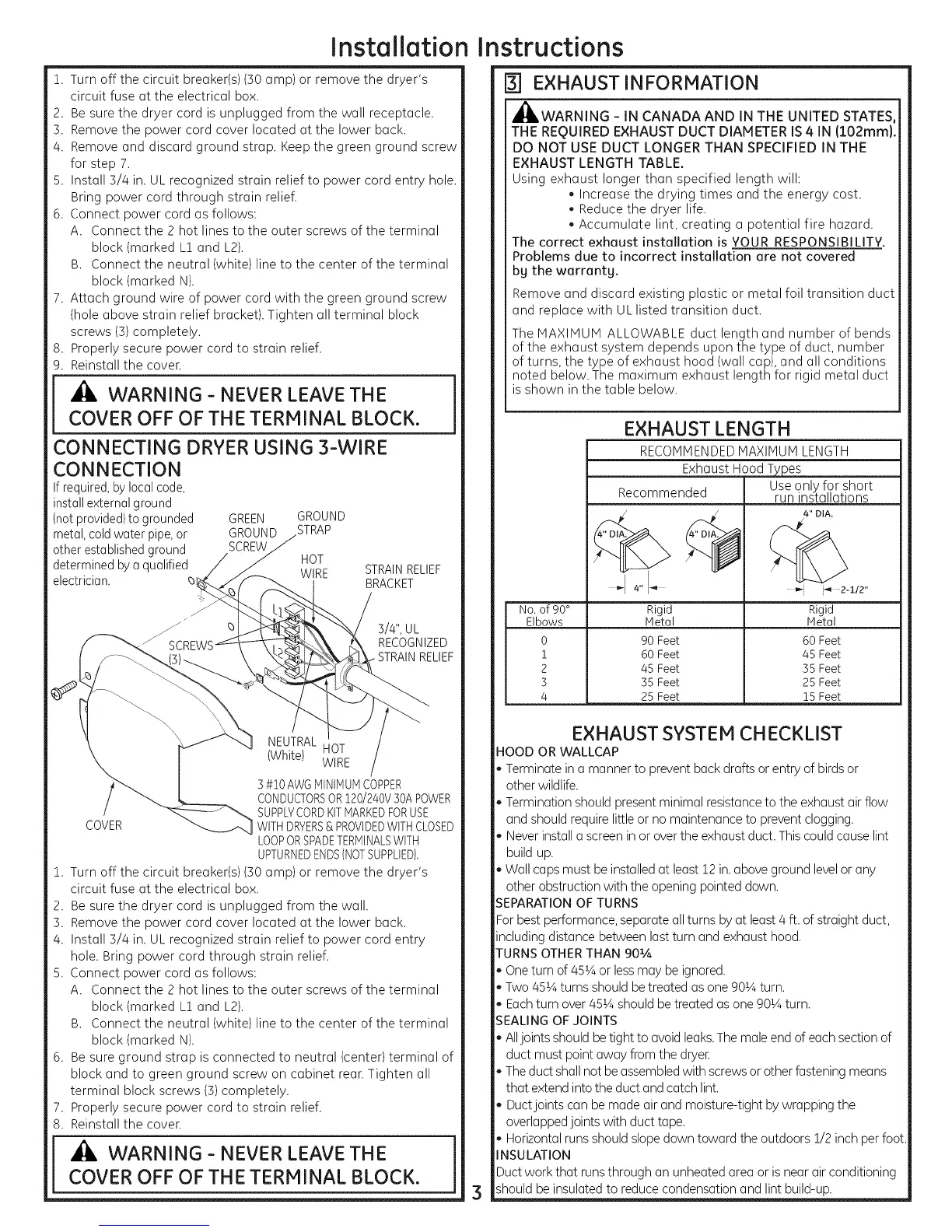
[ _ WARNING-NEVERLEAVETHE ]
COVER OFF OF THE TERMINAL BLOCK.
CONNECTING DRYER USING 3-WIRE
CONNECTION
If required,by localcode,
install externalground
(notprovided)to grounded
metal,cold water pipe,or
other establishedground
determinedby a qualified
electrician.
zJ
GREEN GROUND
GROUND _TRAP
SCREW
HOT
WIRE
STRAIN RELIEF
BRACKET
3/4", UL
RECOGNIZED
RELIEF
NEUTRAL
HOT
(White) WIRE
3 #i0 AWGMINIMUMCOPPER
CONDUCTORSOR120/240V30APOWER
SUPPLYCORDKITMARKEDFORUSE
COVER WITHDRYERS& PROVIDEDWITHCLOSED
LOOPORSPADETERMINALSWITH
UPTURNEDENDS(NOTSUPPLIED).
1. Turn off the circuit breaker(s)(30 amp) or remove the dryer's
circuit fuse at the electrical box.
2. Besure the dryer cord is unplugged from the wall.
3. Remove the power cord cover located at the lower back.
4. Install 3/4 in. UL recognized strain relief to power cord entry
hole. Bring power cord through strain relief.
5. Connect power cord as follows:
A. Connect the 2 hot lines to the outer screws of the terminal
block (marked L1 and L2).
B. Connect the neutral (white) line to the center of the terminal
block (marked N).
6. Besure ground strap is connected to neutral (center) terminal of
block and to green ground screw on cabinet rean Tighten all
terminal block screws (3)completely.
7. Properly secure power cord to strain relief.
8. Reinstall the cover.
COVER OFF OF THE TERMINAL BLOCK.
Instructions
r3-] EXHAUST INFORMATION
_,WARNING - IN CANADA AND IN THE UNITED STATES,
THE REQUIRED EXHAUST DUCT DIAMETER IS 4 IN (102rnrn).
DO NOT USE DUCT LONGER THAN SPECIFIED IN THE
EXHAUST LENGTH TABLE.
Using exhaust longer than specified length will:
• Increase the drying times and the energy cost.
Reduce the dryer life.
Accumulate lint, creating a potential fire hazard.
The correct exhaust installation is YOUR RESPONSIBILITY.
Problems due to incorrect installation are not covered
bg the warrantg.
Remove and discard existing plastic or metal foil transition duct
and replace with UL listed transition duct.
The MAXIMUM ALLOWABLE duct length and number of bends
of the exhaust system depends upon the type of duct, number
of turns, the type of exhaust hood (wall cap), and all conditions
noted below. The maximum exhaust length for rigid metal duct
is shown in the table below.
EXHAUST LENGTH
RECOMMENDEDMAXIMUM LENGTH
Exhaust HoodT _es
Use only for short
Recommended run installations
4" DIA.
4" "I _ i_ 2-I12"
No.of 90° Rigid Rigid
Elbows IVletaI IVletal
0 90Feet 60 Feet
i 60Feet 45 Feet
2 45 Feet 35 Feet
3 35Feet 25 Feet
4 25Feet 15Feet
EXHAUST SYSTEM CHECKLIST
HOOD OR WALLCAP
Terminate in a manner to preventback drafts or entry of birds or
other wildlife.
Termination should presentminimal resistanceto the exhaust air flow
and should require little or no maintenance to prevent clogging.
Never install a screen in or over the exhaust duct. Thiscould cause lint
build up.
Wall caps must be installed at least 12 in.above ground level or any
other obstruction with the opening pointed down.
EPARATIONOF TURNS
Forbest performance, separate allturns by at least4 ft. of straight duct,
including distance between last turn and exhaust hood.
TURNS OTHERTHAN 901A
Oneturn of 451Aor lessmay be ignored.
Two 451Aturns should betreated as one 90_Aturn.
Eachturn over 45_Ashould be treated asone 90_Aturn.
EALING OF JOINTS
Alljoints should betight to avoid leaks.Themale end of each section of
duct must point away from the dryer
Theduct shall not beassembledwith screwsor other fastening means
that extend into the duct and catch lint.
Ductjoints can bemade air and moisture-tight by wrapping the
overlapped joints with duct tape.
Horizontal runsshould slope down toward the outdoors 1/2 inch per foot.
_ISULATION
Duct work that runsthrough an unheated area or is near air conditioning
should be insulated to reduce condensation and lint build-up.
 Loading...