Do you have a question about the GE DPVH880EJ and is the answer not in the manual?
Covers fire/explosion warnings, gas safety, and general precautions.
Specific instruction for ensuring grounding devices are properly reconnected after service.
Explanation of the various parts and codes within the model number.
Guidance on how to interpret the serial number to determine manufacture date.
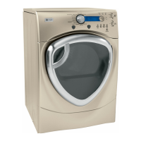
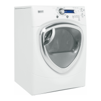
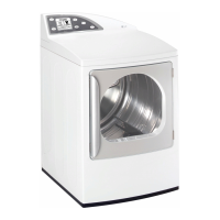
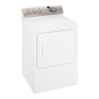
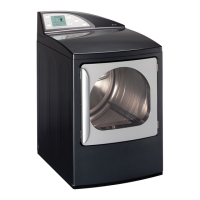
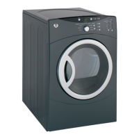
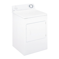
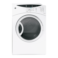
Lists the main features and capabilities of the GE dryer model.
Details on the Power button, Dry Cycles, Timed Dry, and Sensor Dry Level controls.
Information on Dry Temp, Start/Pause, My Cycle, and Display functionalities.
Overview of the Specialty Cycles option and its categories.
Explanation of sensor dry cycles, including dryness levels.
Steps and guidance for using the Timed Dry function.
Details on setting drying temperature, Start/Pause, and My Cycle functions.
Explanation of the dryer's display screen and its messages.
Lists and describes the various categories and cycles available under Specialty Cycles.
Explanation of Extend Tumble, Damp Alert, and Drum Light options.
Details on setting a delayed start and using the control lock feature.
How to adjust display brightness and control sound volume.
Instructions for entering and exiting the Sales Demo Mode.
Information and steps for replacing the dryer's drum lamp.
How to install and use the built-in drying rack system.
Further details on rack installation and using the hanging hook.
Important notes, tools needed, and kit contents for reversing the door swing.
Identification and labeling of various door components and hardware.
Steps for initial door disassembly and reassembling the door handle.
Procedure for reassembling the door handle and chrome cover.
Steps for reassembling the door hinge and inner cap.
Final steps for attaching the door cap and adjusting the strike plate.
Lists what's included in the pedestal kit and the tools required for installation.
Step-by-step guide for physically attaching the pedestal to the appliance.
Final steps for leveling the appliance and assembling the drawer.
Details on compatible washers, location requirements, and clearances.
Steps for installing the brackets to attach the dryer to the washer.
Final steps for securing stacked units and important safety warnings.
Explanation of how air moves through the dryer during operation.
Step-by-step description of a standard drying cycle.
Visual representation of airflow for both gas and electric dryer models.
Labels key internal components within the electric dryer model.
Labels key internal components within the gas dryer model.
Identifies all connectors and their labels on the power board.
Shows both the rear and front sides of the control board assembly.
Detailed procedure for safely removing the dryer's control panel.
Instructions for removing the top panel to access internal components.
Instructions for removing the front panel to access the drum and belt.
Steps for removing the air duct assembly, including sensor rods.
Procedure for removing the drum slide assembly.
Explanation of the door switch's role in dryer operation.
How the moisture sensor works and its importance for drying accuracy.
Details on fuse locations, types, and their protective function.
Procedure for removing the dryer's drive belt.
Steps for installing a new dryer drive belt.
Instructions for removing the dryer drum.
Description of the drum shaft and its associated bearing.
Explanation of the dual idler assembly's function and components.
How the belt switch functions to interrupt dryer operation.
Steps for removing the dryer's drum motor.
Procedure for removing the blower motor assembly.
Important notes and considerations for correctly installing the blower motor.
Instructions for removing the blower wheel from the motor shaft.
Description of the heater assembly, its coils, and power draw.
Steps for removing the triac component.
Details on how heating elements operate during a normal heat cycle.
Description of how heating elements cycle based on temperature.
Description of the burner assembly and conversion to LP gas.
Details on the resistance values for gas valve coils.
Procedure for safely removing the gas valve.
Description of the ignitor, its rating, and resistance.
Instructions for removing the flame detector.
Explanation of the ignitor circuit and how the gas valve operates.
Steps for removing the rack dry Calrod heating element.
Description and removal steps for the inlet safety thermostat.
Description and removal steps for the inlet control thermistor.
Description and removal steps for the high limit thermostat.
Description and removal steps for the outlet control thermistor.
Description and removal steps for the outlet control backup thermostat.
Description and removal steps for the rack dry thermostat.
Steps for removing the power board assembly.
Steps for removing the control board assembly.
Instructions for removing the display board.
How to enter and exit the service test mode.
Details available diagnostic tests and their sequences.
Details on UI, memory, and software version tests.
Details on sensor, blower, and rack dry tests.
Lists error codes, their causes, and recommended corrective actions.
Troubleshooting flowchart for diagnosing electric model complaints.
Troubleshooting flowchart for diagnosing gas model complaints.
Detailed wiring diagram for the electric dryer model.
Detailed wiring diagram for the gas dryer model.
Wiring diagram specific to the rack dry circuit in electric models.
Wiring diagram specific to the rack dry circuit in gas models.
Wiring diagram for the drum motor circuit in electric models.
Wiring diagram for the drum motor circuit in gas models.
Wiring diagrams for the blower motor circuit in both models.
Wiring diagram for the gas valve circuit.
Details on warranty coverage periods, exclusions, and limitations.